intel realsense object center pixel to coordinate coverstion
Hi,
We are trying to detect object coordinate based on object detected using HSV method, following is the code i have used for object detection and coordinate conversion.
cv::Mat gray_img, bin_img, erode_img, dilate_img;
int max_area = 0;
std::vector<cv::Point> large_contour;
std::vector<cv::Point> convex_hull;
rs2::frameset frameset = pipe.wait_for_frames();
frameset = align_to_color.process(frameset);
// To make sure far-away objects are filtered proportionally
// we try to switch to disparity domain
frameset = frameset.apply_filter(depth2disparity);// Apply spatial filtering
frameset = frameset.apply_filter(spat);// Apply temporal filtering
frameset = frameset.apply_filter(temp);// If we are in disparity domain, switch back to depth
frameset = frameset.apply_filter(disparity2depth);auto color = frameset.get_color_frame();
auto depth = frameset.get_depth_frame();
auto colorized_depth = c.colorize(depth);const int w = color.as<rs2::video_frame>().get_width();
const int h = color.as<rs2::video_frame>().get_height();
const int w_d = depth.as<rs2::video_frame>().get_width();
const int h_d = depth.as<rs2::video_frame>().get_height();
Mat frame(Size(w, h), CV_8UC3, (void*)color.get_data());
Mat depth_frame(Size(w_d, h_d), CV_8UC3, (void*)colorized_depth.get_data());auto pf = depth.get_profile().as<rs2::video_stream_profile>();
cv::Mat depth_metric_fp;
cv::Mat depth_raw = cv::Mat(pf.height(), pf.width(), CV_16SC1, const_cast<void*>(depth.get_data()));
depth_raw.convertTo(depth_metric_fp, CV_32FC1);
depth_metric_fp *= scale*1000;
cv::Mat edge_dist;cv::Mat depth_gray,depth_final,blt,cl_edge,dpt_edge;
double minVal;
double maxVal;
Point minLoc;
Point maxLoc;final1 = frame.clone();
cv::cvtColor(frame, hsv, cv::COLOR_BGR2HSV);
cvtColor(frame, gray, COLOR_BGR2GRAY);
cv::inRange(hsv, Scalar(0, 104, 0), Scalar(20, 219, 255), mask);
cv::Mat bw;
cv::Canny(mask, bw, 0, 50, 5);
imshow("Canny ",bw);std::vector<std::vector<cv::Point> > contours;
vector<Vec4i> hierarchy;
cv::findContours(bw.clone(), contours, RETR_LIST,CHAIN_APPROX_SIMPLE);
if (contours.size() == 0) return false;
for (unsigned int i = 0; i < contours.size(); ++i) {
int area = (int)cv::contourArea(contours[i]);
if (area > 1000 && area<10000) {
large_contour = contours[i];
max_area = area;
}
}
if (max_area == 0) continue;
cv::Moments mo = cv::moments(large_contour);
auto result = cv::Point(mo.m10/mo.m00 , mo.m01/mo.m00);
camera_pixel[0] = static_cast<float>(result.x);camera_pixel[1] = static_cast<float>(result.y);
rs2_intrinsics intr = depth.get_profile().as<rs2::video_stream_profile>().get_intrinsics();
auto dist = depth.get_distance(static_cast<int>(camera_pixel[0]), static_cast<int>(camera_pixel[1]));
rs2_deproject_pixel_to_point(camera_coordinates, &intr, button_pixel, dist);float camera_temp[4]={camera_coordinates[0],camera_coordinates[1],camera_coordinates[2],1};
Mat t_camera=cv::Mat( 4,1, CV_32F, camera_temp);
The Values i am getting is -0.23456, 0.14532, 0.345244. Actual values when measured manually we are getting 0.145,0.05,0.345.
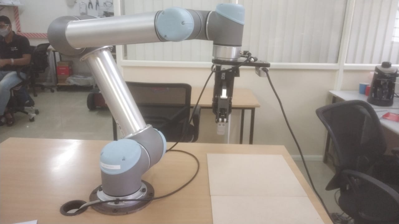
Please suggest me where i am going wrong. the camera is mounted to robot. the camera model is D435i
Thanks
-
Hi Chetankumar Ekzenrobotics The first observation I would make is that you seem to be performing depth-color alignment first and applying post-processing filters secondly. It is recommended that alignment is performed after post-processing is applied.
Also, if your goal is to only obtain the 3D coordinate of the center pixel then you could do so using an instruction called rs2_project_color_pixel_to_depth_pixel. This will convert a single pixel in the color frame to a depth pixel and can be used as an alternative to performing alignment of the entire image. Using this method can provide faster processing than whole-image alignment.
It should also be noted that when using depth_get_distance(x,y) or a similar format of the get_distance instruction, it has been known for the coordinates to be relatively correct at the center of the image but drift when moving towards the edges of the image.
https://github.com/IntelRealSense/librealsense/issues/7925#issuecomment-751335949
Your post-processing filters are applied in the order that is recommended by the post-processing documentation, so that aspect of the script looks correct.
-
Hi MartyG
Thanks for your support, i could able to achieve this.
further to project i am integrating camera with the UR5 robot. I have done camera calibration using the following repo https://github.com/portgasray/ur5_realsense_calibration
And done following tf. the robot is not moving to object location properly. Point1 are the de-projected points from the camera
Please help me where i am going wrong
def callback(point1): print("camera_coordinate",point1) result_1 = [] trans = 0 rot = 0 listener = tf.TransformListener() while not rospy.is_shutdown(): try: (trans,rot) = listener.lookupTransform('/tool0', '/camera_link', rospy.Time(0)) break except : continue matrix2=np.dot(translation_matrix(trans), quaternion_matrix(rot)) point1[0][0] = -point1[0][0] point1[1][0] = -point1[1][0] point1[2][0] = point1[2][0] result_1 = np.matmul(np.array(matrix2),point1) result_1[0][0]=-result_1[0][0] result_1[1][0]=-result_1[1][0] print("object coordinates",result_1) move_to_pos_1(result_1) return result_1 -
-The robot is moving, but not to the exact position
- I am using ROS melodic for UR
- Realsense ROS is from (https://github.com/IntelRealSense/realsense-ros) this, presently i am using python package for the object detection
-
The librealsense and ROS version numbers are listed in the ROS launch log in the section of the log shown in the example below.
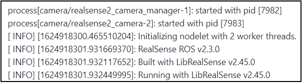
It is important for the ROS wrapper version to be matched as closely as possible with the specific librealsense version listed in a particular wrapper version's release notes. Having said that, your RealSense ROS project does seem to be functioning well enough for the robot to be able to move.
Would you describe your robot's movement as drifting off-course from the intended route as though it has become lost?
-
Okay, thank you very much. So it is not a case of a wheeled mobile robot becoming 'lost' on a route, but instead a robot arm interacting with the position of an object (hand-eye calibration with the previously mentioned ur5_realsense_calibration package).
The GitHub of the package indicates that it makes use of ArUco image tags. If you are using ArUco and the camera's IR emitter is enabled and projecting a semi-random dot pattern onto the scene, this may make image tags more difficult for the camera to read if the dot pattern is overlaid on the tags.
RealSense 400 Series cameras can alternatively use the ambient light in a scene to analyze surfaces for depth detail instead of analyzing the projected dots cast on a surface. Would it be possible to turn off the camera's IR emitter and see whether your results improve, please?
The IR emitter can be disabled with Python scripting or from within the RealSense ROS wrapper.
ROS
https://github.com/IntelRealSense/realsense-ros/issues/1379#issuecomment-691453842
PYTHON
https://github.com/IntelRealSense/librealsense/issues/8978#issuecomment-833612704
Please sign in to leave a comment.
Comments
7 comments