how do we get a result like in this picture?
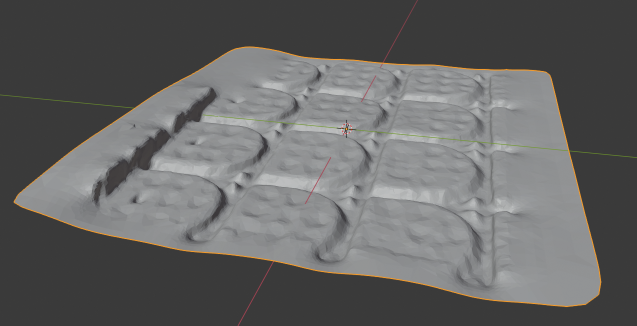
We got this model with the default parameters of the itSeez3D-Software. How do we get a similar result in the Software "RealSense-Viewer"? The object, that is represented, is a concrete slab with notches.
Which parameters do we have to change? Is there any documentation of which parameter does what?
-
You did not specify which model of RealSense camera you are using. In general though, for high quality close-up scans like this, if you would like to achieve a higher quality image then the D415 model is better suited than the D435 model to scanning a small, non-moving area. It has around 2.5x the image quality of the D435 and its optimal resolution is 1280x720. D415 has a smaller field of view than the D435, but that should not make a difference at the close range that you will be scanning from.
If you already have a D435 camera then you could try applying a camera preset configuration called 'High Accuracy'. This can be selected in the RealSense Viewer by using the preset selection menu near the top of the Viewer's options side-panel to select 'High Accuracy' from the menu instead of the default 'Custom' setting.
Further details about presets can be found in the link below.
https://github.com/IntelRealSense/librealsense/wiki/D400-Series-Visual-Presets#preset-table
-
Not every function in the RealSense SDK is documented. For example, the majority of the 'Advanced Mode' settings are not documented. This was because these values interact with each other in complex ways and so Intel chose to control them with machine learning algorithms instead. You are free to do trial and error experimentation with the Advanced Mode values to see how it affects the image though.
If you need to get the camera closer to the object without going below the camera's minimum distance and causing the image to break up, there are a couple of methods that you can try.
1. Reduce the resolution of the camera. This would negatively impact accuracy and image quality, so it is likely not the best option for you in this case.
Or 2. Increase the 'Disparity Shift' value in the Viewer. This reduces the camera's minimum distance, enabling you to get the camera closer to the observed object. It also reduces the maximum depth sensing distance at the same time, though this should not be a problem if you are doing very close range scans.
Intel has a guide for tuning the 400 Series camera to help achieve the results that you are aiming for. Section 5c of the guide explains about Disparity Shift.
Section 8 also explains how you can minimize the 'Depth Units' setting from its default of '0.001' to current minimum of '0.0001' to improve results at very close range. Around 20 cm distance from the object is the practical limit of minimum distance though before the camera's left and right imagers get confused..
-
As already mentioned we don't need to get closer to the object. We need a way to get the depth information of the in the picture marked area. Only of this area!
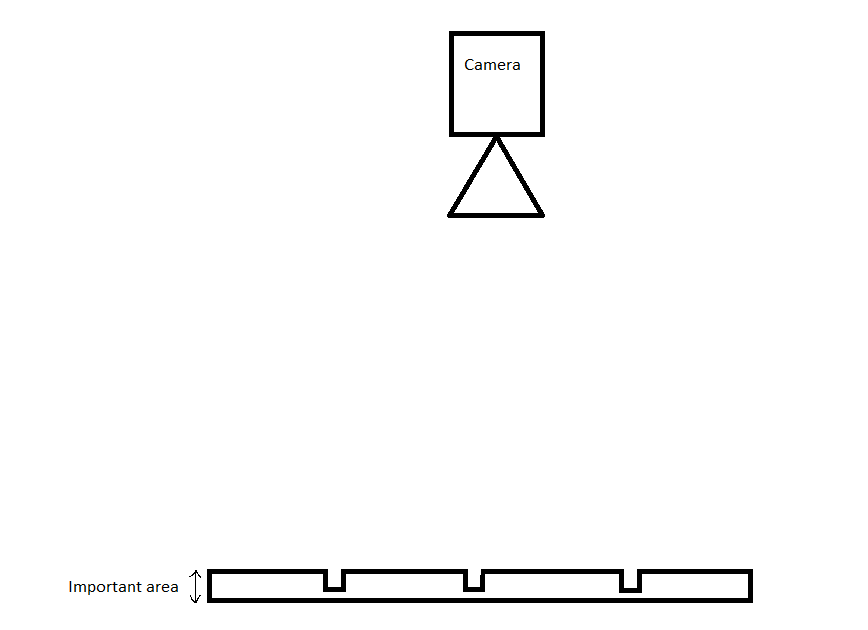
Which parameters or settings in the Software are necessary to get the depth information of this area?
"Around 20 cm distance from the object is the practical limit of minimum distance though before the camera's left and right imagers get confused."
The camera is 40 cm to 50 cm from the object away, if we put it nearer, we don't get the whole slab on the picture. . -
If you used ItSeez3D with the D415 then I am guessing that you used their Scanner 2.0 for Windows software to do the scan of the concrete slab that you provided, please?
https://itseez3d.com/blog/itseez3d-scanner-2-0-for-windows/
If this is the software that you used (to create a solid mesh model) then there would be no way to replicate that directly in the RealSense Viewer, as the Viewer renders 3D detail as a Point Cloud instead of a solid mesh. To get a 3D model like the one in the image would require a two-step process:
1. Export a point cloud scan of the slab from the RealSense Viewer as a point cloud '.ply' format file.
2. Import the ply file into 3D model software to convert it into a solid mesh. The fastest way to do this conversion would be with a program called MeshLab. The link below has a guide to converting a ply exported from the RealSense Viewer to a solid-mesh model in MeshLab.
https://www.andreasjakl.com/capturing-3d-point-cloud-intel-realsense-converting-mesh-meshlab/
Please sign in to leave a comment.
Comments
5 comments