CAD model for the OEM Calibration Target
Hi! I am designing a physical fixture to hold the D415e and the Intel OEM Calibration target so that I can do the OEM calibration procedure. There are some rough overall dimensions listed on the calibration target's product page, but I'm hoping that you have a CAD model of the target so I can design a proper fixture to hold it accurately with respect to the D415e. Do you have CAD of the target (STEP, IGS, etc)? Thanks!
-
Hi Matt There is not a CAD file available for the OEM calibration target product, unfortunately. There is also not a CAD file for the FRAMOS D415e industrial RealSense camera, as it is a product not manufactured by Intel.
-
Copy that. On a similar note, how do I interpret the red and yellow stars in this image?
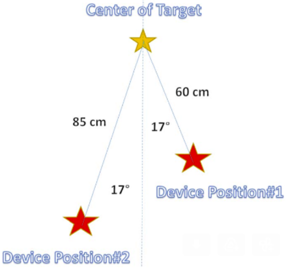
- Is the yellow star the center of the "crease" of the OEM calibration target? Without the CAD model, I'll just have to try to do a precise measurement of the target with a scale/tape-measure/etc to find the X, Y, Z coordinates of that point. But can you confirm that "Center of Target" means the center point of the "crease" of the target (i.e. the joint where the two checker boards meet)?
- Is the red star the depth origin of the D415 or some other feature on the camera enclosure?
The context here is that I'm trying to do an accurate OEM calibration on the D415 and I need to accurately locate the camera and target with respect to each other.
Thanks,
Matt
-
The above image originates from the Intel guide linked to below.
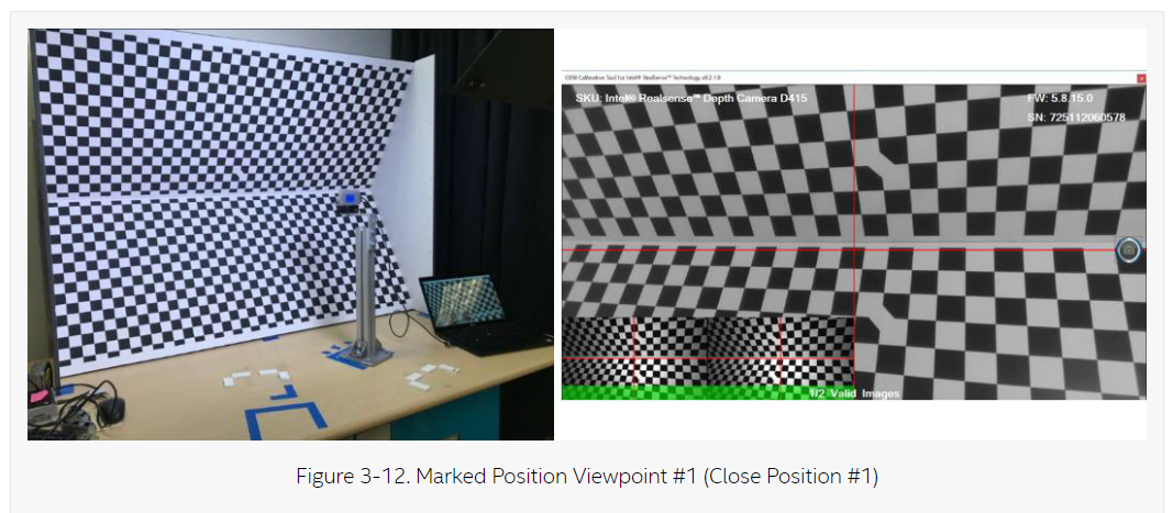
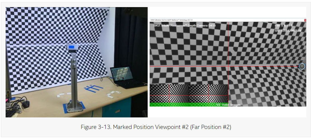
The image in the guide directly below the star image does indicate that the camera is directed at the center horizontal 'crease' of the OEM calibration target board. The camera is first placed in Position 1 and a capture is taken. The camera is then moved to Position 2 and another capture taken, so that two images are obtained. So the red stars simply indicate the position of the camera relative to the OEM target board (represented by two blue tape markings on the table surface in the illustrations below).
CAMERA POSITION 1
CAMERA POSITION 2
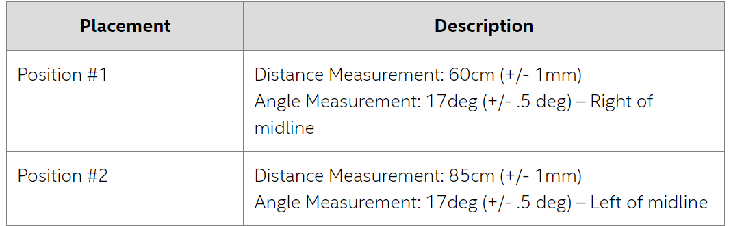
The table below describes how far from the board the camera should be placed, and how far to the left and right of the target board's midline, for each camera position, as well as the number of degrees that the camera should be rotated horizontally to face the board at an angle instead of straight ahead.
-
Hi MartyG, thanks for the response. Can you clarify to what point on the camera the 60 cm and 85 cm distances are referring to? Since the tolerance on that distance is fairly tight (+/- 1mm) it matters what part of the camera that measurement is referring to. Is it to the depth origin, the threaded hole on the bottom of the camera, the center of the camera's front glass, etc?

Please sign in to leave a comment.
Comments
5 comments