D455 for vehicle Forward Collision Warning
Dear Team,
I am working on an research/industrial project for the development of forward collision warning systems for vehicles. The system shall be to warn/break the vehicle in-case a collision with vehicle in front in unavoidable. I intend to use just a stereo camera in order to realize this system. My question is if D455 is suitable for object detection and distance calculation for upto 20 Meter range? If not then is there any other model which could be used?
Secondly is it possible to get the L/R video frames in Matlab/Simulink on Windows for further processing?
-
Hi Farashes The ideal depth sensing range for the D455 model is stated by the data sheet document for the 400 Series cameras to be 0.4 meters to 6 meters.
https://dev.intelrealsense.com/docs/intel-realsense-d400-series-product-family-datasheet
The D455 is twice as accurage over distance as the D435 / D435i models, meaning that at 6 m range the D455 has the same depth measuring accuracy that the D435 / D435i does at 3 meters.
As distance of an observed object / surface from the camera increases, the depth error increases linearly. This phenomenon is known as RMS Error. Whilst the ideal maximum distance for the D455 in terms of accuracy is 6 meters, you could still obtain a good depth image at 10 meters range.
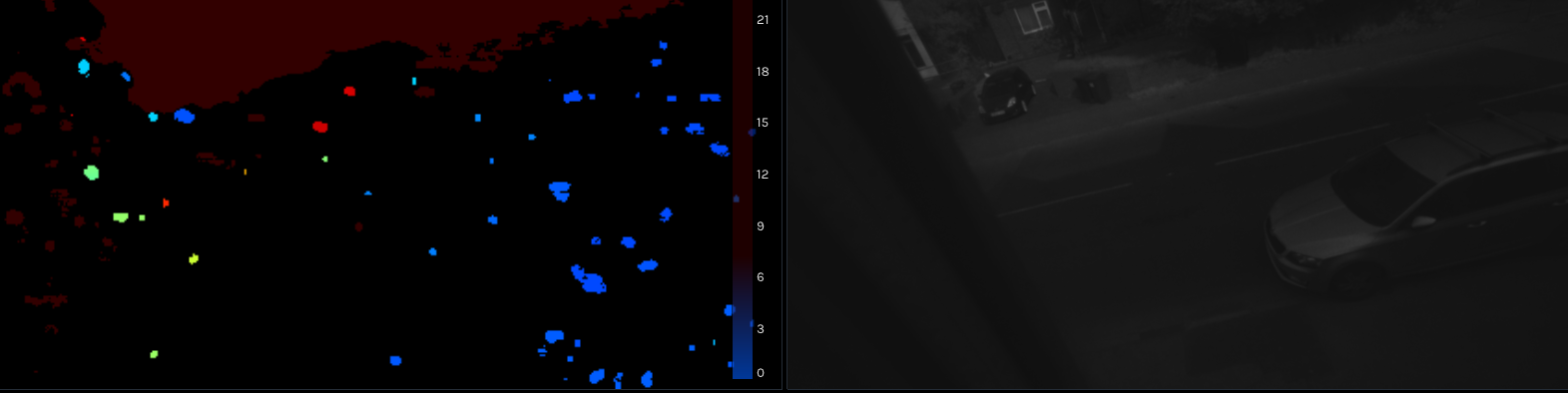
At 20 meters range it is unlikely that you will obtain useful depth data. The image below that I created for this discussion points the D455 out of a window to observe the far side of a street up to 21 meters. The left and right infrared images can observe clearly at that distance though.
Even at 10 meters depth range though the D455 should be able to provide a very good depth image of a road with cars, as demonstrated by the YouTube video in the link below where a D435 model was mounted on a vehicle travelling at full speed with vehicles driving towards the camera from the opposite direction on the other side of the road.
https://www.youtube.com/watch?v=OwJmCyAn3JQ
The D455 is the best RealSense model available for long range accurate depth sensing.
Below is a listing for a MATLAB wrapper script for displaying unrectified Y16 left and right infrared that a RealSense user shared.
% Make Pipeline object to manage streaming

pipe = realsense.pipeline();

%enable the IR streams

cfg = realsense.config();

cfg.enable_stream(realsense.stream.infrared, 1, realsense.format.y16)

cfg.enable_stream(realsense.stream.infrared, 2, realsense.format.y16)

% Start streaming all streams

profile = pipe.start(cfg);

%in order to get this to work, frameset.m needs to be corrected. all

%instancces of int64_t needs to be changed to int64 in that file.

% Get streaming device's name

dev = profile.get_device();

name = dev.get_info(realsense.camera_info.name);

% Get frames. We discard the first couple to allow

% the camera time to settle

for i = 1:5

fs = pipe.wait_for_frames();

end

frameCount =0;

while frameCount < 50

  frameCount = frameCount+1;

  fs = pipe.wait_for_frames();

  ir1 = fs.get_infrared_frame(0);

  ir2 = fs.get_infrared_frame(1);

  irdata1 = ir1.get_data();

  irdata2 = ir2.get_data();

  img1 = reshape(irdata1, 1280, 800);

  img2 = reshape(irdata2, 1280, 800);

  figure(1)

  imshow(img1)

  figure(2)

  imshow(img2)

end

% Stop streaming

pipe.stop(); -
Got it.
So that means we could theoretically use the IR images for vehicle detection using deep-learning methods and then get distance using Realsense APIs in the range of around 20m. What would be the depth error in this case?
For range of 10m and below we can then theoretically create an IR and Stereo-images fusion to reduce false positives.
I am assuming that all of the depth information (IR+Stereo) could be retrieved inside our Matlab/Simulink model using your APIs.
Does this approach makes sense?
-
The section of Intel's camera tuning guide linked to below provides a formula for calculating RMS error.
There is not a visual representation for D455 of RMS error's linear increase over time. There is one for D415 vs D435 though. As the D415 has around half the RMS error over distance of the D435 model, roughly projecting the D415 line's rate of ascent (as shown by the green line with the black extension line that I added) might provide a rough estimate of how RMS might increase as distance moves towards 20 m (with the graph below only showing up to 5 m).
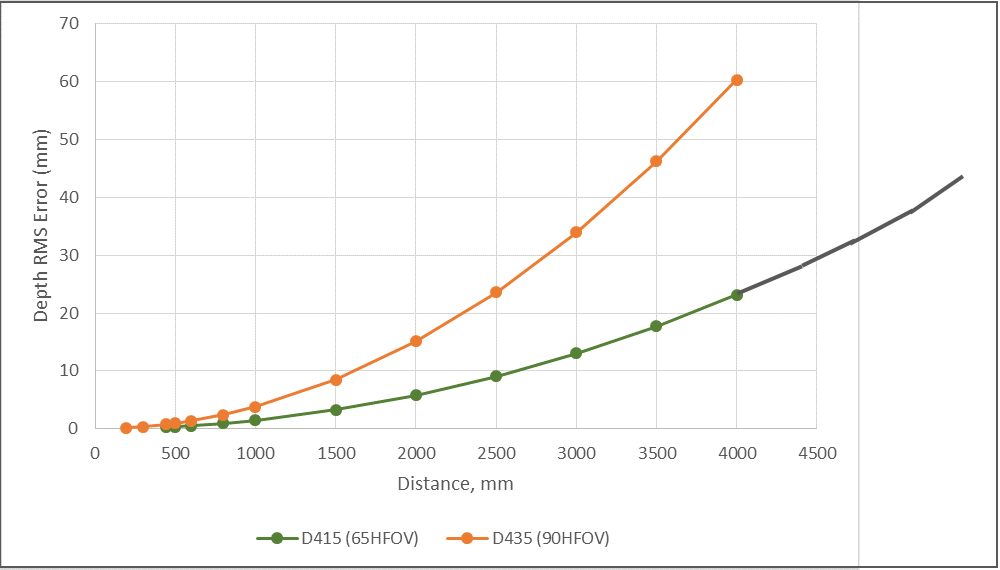
As the 20 m depth image provided earlier suggests, RMS error at 20 m may scale to a point where the depth coordinates are not usable.
As well as the infrared streams being accessible through the RealSense MATLAB script with the code provided earlier, depth data is also accessible. The MATLAB wrapper has two example scripts, depth_example.m and depth_view_example.m
https://github.com/IntelRealSense/librealsense/blob/master/wrappers/matlab/depth_example.m
https://github.com/IntelRealSense/librealsense/blob/master/wrappers/matlab/depth_view_example.m
Typically though, alignment is between depth and color. It is possible to map together depth and infrared, as demonstrated by the C++ OpenCV example program linked to below. Usually it is not done though, as the left infrared is already perfectly aligned with the depth map anyway as they originate from the same imaging sensor.
-
Just for my understanding, I would refer to what you wrote above: "The left and right infrared images can observe clearly at that distance though".
This means that the image on the left with distance axis is an IR-Depth map where one can expect good depth accuracy in 20m range. Correct?
And the image on right is the corresponding IR image which we could theoretically use for object detection? One should eventually be able to correlate both images to find the distance to the object.
-
The 20 m image shown earlier was separate Depth and Left IR images of detail observed at 20 m, with depth on the left and IR on the right. Distance does not restrict the range of the IR image, although the camera's built-in projector and the IR dot pattern cast from it will not be able to reach to 20 m.
The dot pattern is helpful in analyzing surfaces for depth information, as the dots cast onto an objects surface can be used by the cameras as a 'texture source' to analyze for depth detail. It would not be able to help though with depth analysis of objects that are 20 m away as the pattern projection could not reach that far. In the absence of a dot pattern being cast onto objects that can then be read by the camera, the amount of detail on the depth image can noticably reduce.
Projection range can be extended with an external IR pattern projector that has a higher power level than the built-in projector, though using an external projector may not be viable for an automotive project if the equipment has to be incorporated into the vehicle.
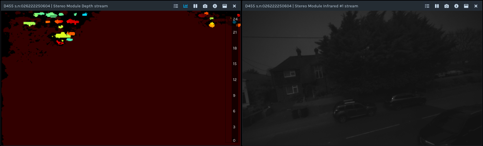
I re-tested with 20 m distance and was able to achieve a significantly more detailed depth image if the Advanced Mode option called Second Peak Threshold was set to '0' instead of its default value of '325'. The red color on the depth shading represents far-distance depth detail.
The MATLAB wrapper has an example program for accessing Advanced Mode called advanced_mode_example.m
https://github.com/IntelRealSense/librealsense/blob/master/wrappers/matlab/advanced_mode_example.m
The link below discusses the Second Peak Threshold option.
Please sign in to leave a comment.
Comments
5 comments