D435 won't detect small walls
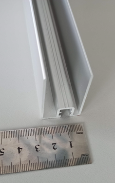
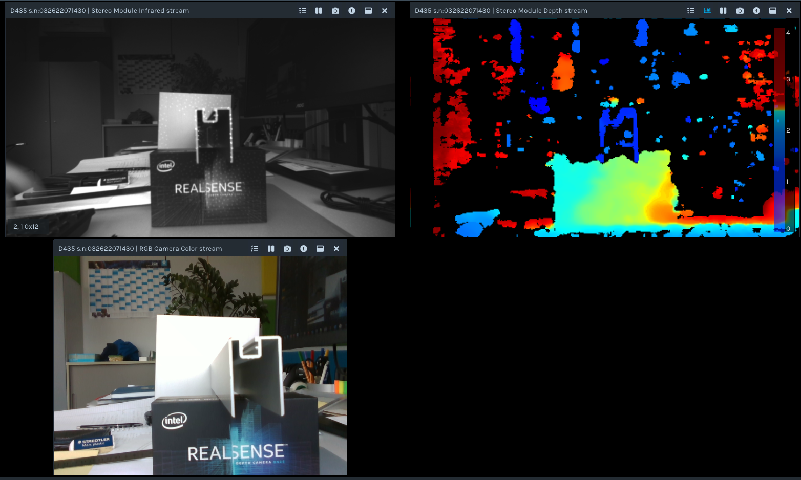
I'm trying to detect aluminum profiles seen from the front side, as seen in the image below.
I used the Threshold Filter to get rid of the background, played with the exposure and auto exposure and with the spatial filter settings, The resolution was set to 1280 x 720. But I wasn't able to get any depth data on the thin profile walls. They are just missing in the image, and it seems to me that the lateral resolution is just not high enough to resolve those tiny lines.
1. Does any one know how many pixels need to be on an objekt to be detectable?
2. Are there settings, that allow for higher lateral accuracy? I can a accept temporal deterioration.
Thanks for any hints.
-
Hi Bbiehler It has been stated in a past case by the Chief Technical Officer of the RealSense Group at Intel (agrunnet) that for an object to be reliably trackable, it should have at least 9 pixels.
https://github.com/IntelRealSense/librealsense/issues/4175#issuecomment-507448389
Could you confirm for me please which part of the scene is the aluminium part that you are trying to track - the object the arrow is pointing to that looks like a plant pot, or the frame-like shape atop the RealSense packaging box?
-
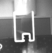
Yes, I can confirm that it is this U-shaped object. For a better understanding there is another picture of the extruded profile as seen from diagonally above and the part zoomed in from the other picture.
I was not aware of the 9 pixel requirement, thank you.
That means, if I have a minimum wall thickness of 2 mm and need 9 pixel on it, I need to adjust the distance to the point where I get 4.5 pix/mm. With 1280x720 pixels available, this will cover a FOV of around 284 x 160 mm². The opening angle of the long axis is according to datasheet phi = 86°. Then the maximum distance to detect such a object will be d = <lenght of long axis> / (2 * tan(phi/2)) = 284 mm / (2 * tan(43°)) = 152 mm.
Problem is, usually the D435 won't give any reading for distances this close. Is there a way to make the camera look for correspondences in a wider area and therefor getting a closer minimum distance? I will be happy with a single frame per second, so time won't be a problem.
Thanks in advance
-
115 mm = 0.115 m. The minimum distance of the D435 / D435i is 0.1 meters. So you are up against the default minimum limit. You can though reduce the minimum distance by (a) using a lower resolution, or (b) increasing the value of a setting called Disparity Shift.
The optimal depth accuracy resolution for D435 is 848x480 (it is 1280x780 on the D415 model), so you may obtain better measurement accuracy simply by dropping down a resolution to 848x480 if that is possible for your project.
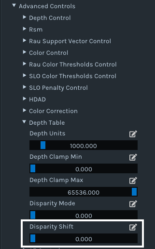
If you are testing in the RealSense Viewer, the Disparity Shift option can be found under the Depth Table sub-section of the Advanced Controls category of the options side-panel. Its default value is '0'. I recommend trying a value of '50' to reduce the minimum distance. You can change the value with the slider control or left-click on the pencil icon to manually type a value in.
How the Disparity Shift setting works is that increasing its value reduces the minimum depth distance (MinZ) and so allows the camera to get closer to an object / surface, but also reduces the maximum observable depth distance (MaxZ). For close-range scanning, this reduction in maximum distance does not matter so much though.
For sensing thin-width objects, you may also obtain better results by aligning depth to color, like in the case below where depth to color alignment is used to assist the scanning of a thin toothpick.
https://github.com/IntelRealSense/librealsense/issues/8228
-
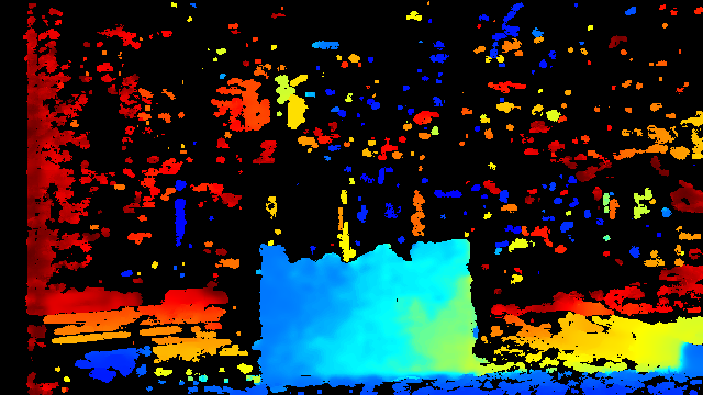
So I changed the setup a bit: Distance to the objekt is now 0.1 m, resolution 848x480, and I worked with the disparity shift in the range of 40 to 150. The Depth units are 0.0001.Still the Post-Processing ThresholdFilter was set to 0 / 0.4 m Observation:
Whene changing the disparity shift part of the walls of the profile appear and disappear. Lots of artefacts start to appear in the background.How much of the part is visible depends strongly on the orientation of the part. I was not successful to get a single image with the entire profile wisible.
Below is the part in question.
Decreasing the distance from object to camera did not improve the results.Changing the resolution back to 1280 X 720 resulted in
No improvement either.
Any more ideas? Or is this simply the limit of what is possible at the moment?
-
Thanks very much for the new information. I agree that Disparity Shift does not seem to be helpful in this particular application, so please set that option back to '0'.
Since the Threshold Filter does not change the minimum distance of the camera, it is only useful in this case if you wish to exclude background information behind the observed object.
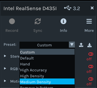
You could try setting the Medium Density visual preset, which provides a balance between accuracy and 'fill rate' (the amount of detail).
Maximizing Laser Power to '360' may also provide some additional detail, as increasing Laser Power can make a depth image less sparse (fewer holes / gaps).
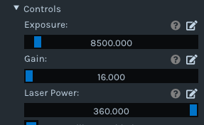
The inside walling of the frame object may benefit from having additional illumination projected within it, as it looks dark even with the IR emitter dot pattern projected onto it. Maximizing Laser Power should increase the intensity (brightness) of the dots on the infrared image, as dot visibility is tied directly to Laser Power - a higher value = more visible and a lower value = less visible.
-
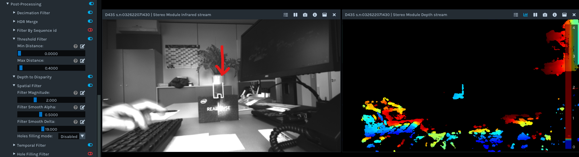
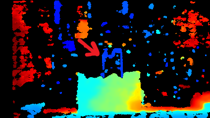
Still no success. I started with the medium density presets, adjusted the exposure time and turned the laser power to its maximum, but did not see improvements:
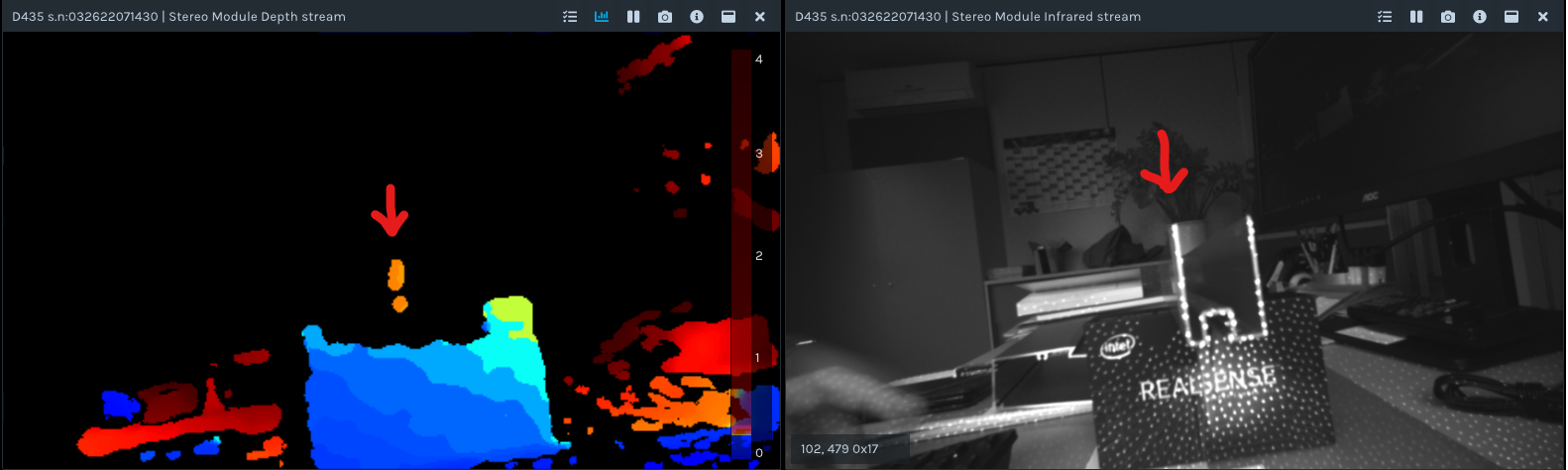
The red arrow points to the left wall of the profile in question.
When again playing with the disparity shift, I found a setting that made the profile show:
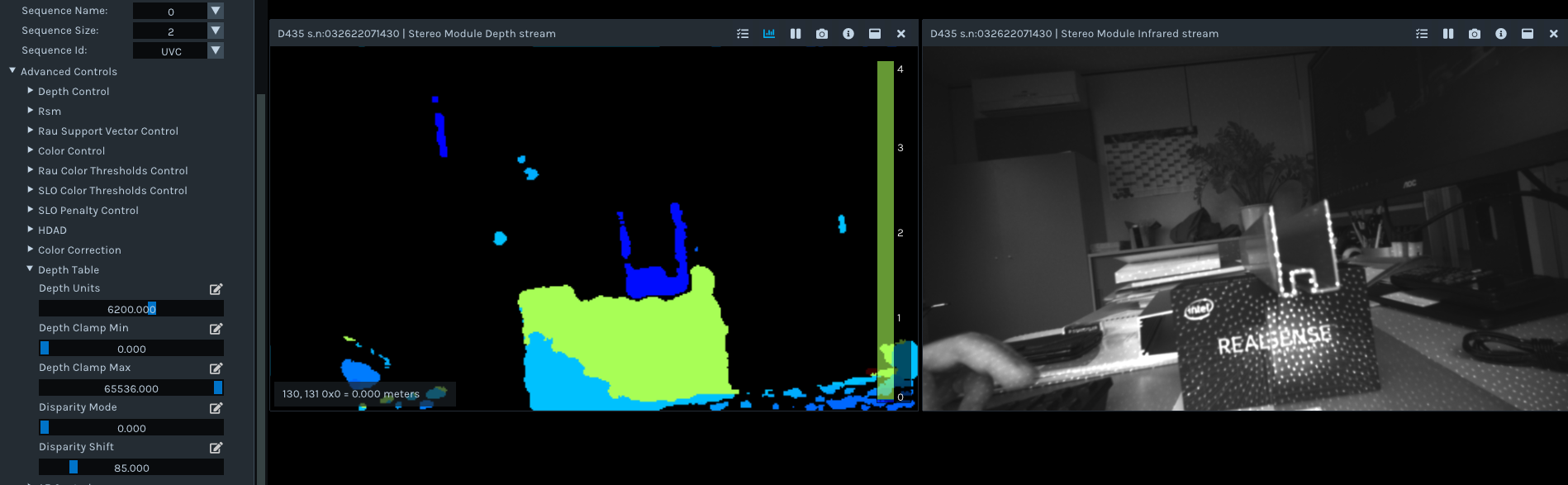
Anyway this setting is very touchy and depends on the exact position of the profile. Just not stable.
What exactly does the parameter "disparity shift" do math wise? It doesn't increase the window, where the camera is looking for correlations, does it?
-
Information about disaprity and disparity shift can be found in the link below.
https://github.com/IntelRealSense/librealsense/issues/3039#issuecomment-456975023
Disparity shift is also covered in point 3 of the section linked to below, with an accompanying chart.
Please sign in to leave a comment.
Comments
7 comments