Custom calibration (D410 and D415)
Hi all.
I am currently part of a team developing an IoT device with an Intel RealSense D410 (sometimes D415) connected to an SBC running Yocto/Linux. In our setup we would like to calibrate the device when everything is assembled. This means that we are currently developing a python script with calibration for the D410 using OpenCV. As a result of this we have been looking into how we can transfer the calibration values into the D410, preferably without using the librscalibrationapi since that would be an additional package we would have to include and maintain in our Yocto build.
TLDR questions:
1. Will the tm2-class set_extrinsics and set_intrinsics functions (or similar) be available for the D410 in the near future?
2. Is there a way for us to translate OpenCV calibration values into the D410 calibration table?
3. Are we missing something and/or overthinking this?
Long version:
What we have found so far is that if it was a "tm2"-device (tm2 references the pyrealsense2 class https://intelrealsense.github.io/librealsense/python_docs/_generated/pyrealsense2.tm2.html#pyrealsense2.tm2) we could use the set_extrinsics and set_intrinsics functions. The first question is therefore will similar functions be available for the D410 (which we believe is an "auto_calibrated_device"-device) at some point in the near future?
A second observation we have made is that it is possible to read out and write back a "calibration table" (using get_calibration_table, set_calibration_table, and write_calibration - https://intelrealsense.github.io/librealsense/python_docs/_generated/pyrealsense2.auto_calibrated_device.html#pyrealsense2.auto_calibrated_device). This table is also available from the Intel.Realsense.CustomRW-tool and seems to be meant for use when using the auto-calibration features of the D410. The second question is therefore is there a way for us to translate the calibration values from OpenCV (focal lengths, principal points, and distortions) into the D410 calibration table?
Third point is simply are we missing something? We have been looking into this to simplify the assembly/production process of the device. We are still looking into the final process (how many images/positions, the physical setup, etc.) but maybe we are looking at this in a completely wrong way?
Hopefully you can help us.
Best regards
Lars
-
Hi Lch The opening point I would make is that the Dynamic Calibrator is not the only way to calibrate a RealSense camera. Though it was the original means of calibrating 400 Series cameras, the On-Chip Calibration system that is incorporated into the firmware was later introduced.
https://www.intelrealsense.com/self-calibration-for-depth-cameras/
https://dev.intelrealsense.com/docs/self-calibration-for-depth-cameras
Although it is launchable from the RealSense Viewer program, it can also be activated with Python API code.
The self-calibration white paper (linked to above) states that "These new features work on any Operating System or compute platform, as they simply invoke new Firmware (FW) functions inside the ASIC. As a result, they also have essentially zero load on host CPU and are very fast".
If you would prefer to continue with your current OpenCV / Python approach, I will be happy to do my best to answer your questions above. Thanks!
-
Hi MartyG
Thanks for the quick feedback.
We will take a look at the On-Chip Calibration to see if we can make it work. A quick followup question: The linked paper mentions version 2.33 of the LibRS (I expect LibRS is librealsens). We are currently running version 2.31 in our Yocto build, do you know if we are going to run into problems? In a quick test it didn't seem to matter, but if you know something that could be very helpfull.
Best regards
Lars
-
Yes, LibRS is shorthand for librealsense. You may also see it described as LRS, librealsense2 or RealSense SDK 2.0 in some places..
Whilst librealsense 2.31 is certainly usable, I would encourage you to update to a newer version when you have the opportunity to, so that the supported RealSense technology and features available to your project do not fall too far behind (2.31 is from December 2019). For example, an old SDK version may limit your ability to upgrade your project with newer RealSense camera models such as a D450 module (the Depth Module version of the D455 camera).
-
Since we are building our own enclosure, we would like to compare calibration results between our own method and the on-chip calibration method, especially regarding the distortion coefficients. This brings me back to one of my original questions: Is there a way to convert between “human readable” values and the raw calibration tables?
If we read out the intrinsic parameters through the python API (v. 2.39 or 2.31) the distortion coefficients are all 0. After reading through some posts this seems to be because the images are already rectified which is OK. If we instead use the CustomRW-tool we can read out the “human readable” intrinsic parameters (i.e.: .\Intel.Realsense.CustomRW.exe -r) but no matter what calibration table we use the parameters seems to be the same. If we then read out the raw output (e.g.: .\Intel.Realsense.CustomRW.exe -r -raw 19) the raw output seems to change as expected. Are the “human readable” values always from the factory calibration or are they simply not modified by our new calibrations?
-
The coefficients are deliberately all set to zero on the 400 Series cameras, so this is not an indication of a problem.
https://github.com/IntelRealSense/librealsense/issues/1430
Calibration reading methods such as CustomRW, rs-enumerate-devices - c or the SDK tool rs-sensor-control should return human-readable matrices of whatever the current stored intrinsic / extrinsic values are, not the original factory calibration (unless it is a new camera and has not had an updated calibration written to it yet, of course).
If you created your own calibration application then it would need to be able to write an updated calibration to the camera hardware in order for those calibration values to be persistent. Otherwise it would be the same result as performing a calibration with an SDK calibrator tool but not saving the calibration at the end of the process.
-
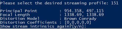
It seems that the output from the two programs is the same as the information you can get from the SDK, i.e. all calibration coefficients are 0:
rs-enumerate-devices -c: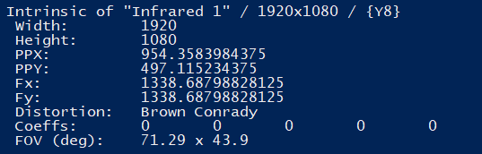
rs-sensor-control:

An additional observation is that if you select an unrectified stream (e.g. stream 150 shown above) you get an error:

This was surprising since the intrinsics for an unrectified stream would be especially helpful if you wanted to correct the image yourself.
In both cases the output is different that the output from the CustomRW-tool:
Here the distortion coefficients are listed, they are small, but they are non-zero.
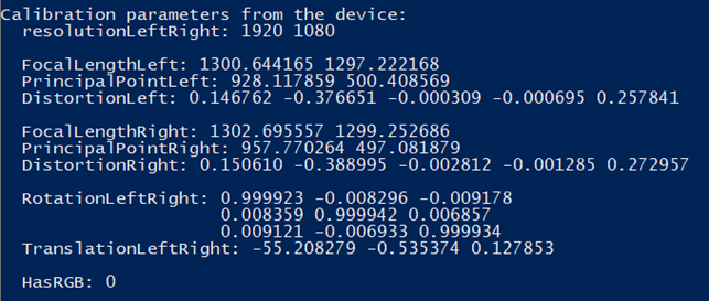
Regarding the output of the CustomeRW-tool. As I mentioned it seems that the human readable values do not change but the raw readout does:
First image is a factory reset camera:
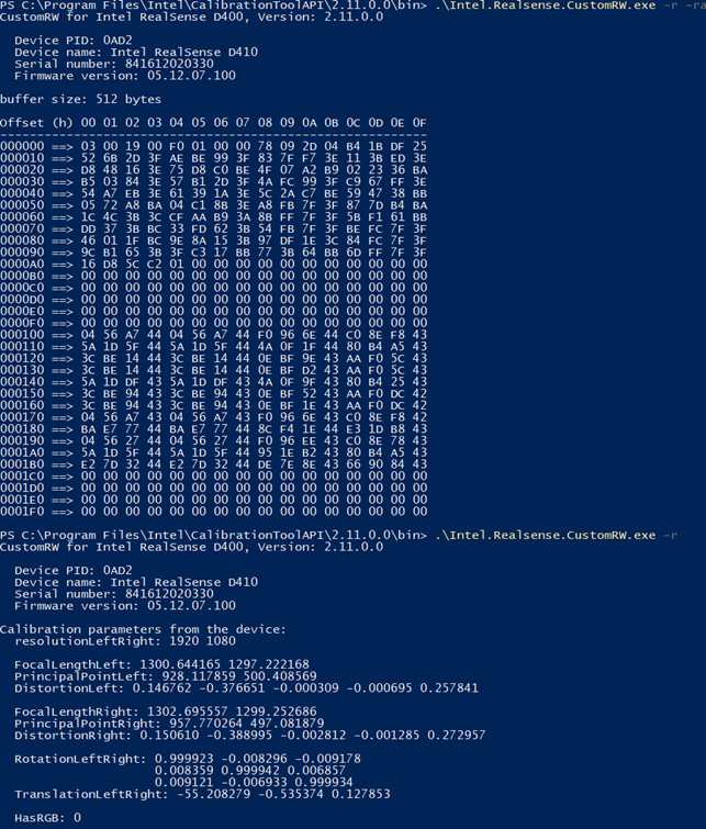
The second image is the same camera but it has been calibrated (using the auto-calibrate function) and the new calibration table has been saved/written to the camera:
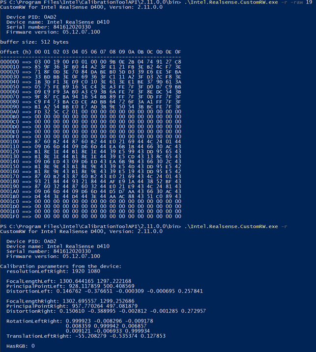
As you can see the ‘raw’ output is different between the two images, but the human readable outputs are the same. Are we doing something wrong or is there another way to compare the changes between the two calibrations?
-
The unrectified stream is Infrared at 1280x800 and 25 FPS (it is important that 1280x800 is used and not 1280x720). This mode is used for camera calibration. All other modes are streaming after rectification.
As mentioned by Dorodnic the RealSense SDK Manager in case #1430 linked to above, the SDK estimates fx, fy, ppx and ppy without using the coefficients.
-
According to the calibration white paper (https://dev.intelrealsense.com/docs/d400-series-custom-calibration-white-paper ) the unrectified stream for the D410 and D415 is the 1920x1080 Y16 stream. The 1280x800 is for the D420/D430/D435.
-
Yes, our own calibration is done using the 1920x1080 y16 stream. The auto calibration test we did was done using the “zoomed-in” stream 256x144 z16.
Today we made a new test to test the two ways of writing a calibration to the camera:
- Writing a calibration table through the SDK
- Writing an XML file using the CustomRW-tool
First, we did the following:
- Reset the camera
- Read out the calibration table and the human readable values from the camera
- Construct an XML files with values different than the default values
- Write the XML file to the camera using the CustomRW-tool
- Read out the calibration table and the human readable values from the camera
- Compare the calibration tables and human readable values
- The two calibration tables were different – as expected
- The human readable values were different – as expected
- The human readable values from after the calibration update was the same as the XML values – as expected
After this we made an additional test:
- Reset the camera
- Read out the calibration table and the human readable values from the camera
- Write a new calibration table to the camera through the SDK
- Here we use the calibration table generated in step 5 in the first test. This means that we would expect the human readable values to be the same as the values generated in step 5 in the first test and in the XML file from the first test.
- Read out the calibration table and the human readable values from the camera
- Compare the calibration table and the human readable values
- The two calibration tables generated in step 2 and 4 are different – as expected
- The two calibration tables generated in step 5 in the first test and step 4 in this test are the same - as expected
- The human readable values generated in step 2 and 4 are the same – NOT as expected. Here we would have expected the human readable values to be different and the values generated in step 4 to have been the same as the XML values used in the first test.
In other words:
It seems that if you use the SDK to write a calibration table the human readable values are not updated. But if you write an XML with the human readable values the calibration table is updated.
As we understand it, this means that if we use the auto calibration tool, we can never read out the actual distortion values which is a shame since we would like to use them as an evaluation of our own enclosure. Do you know if this is intended functionality or if it is a bug?
-
If I understand correctly, test 2 is mixing together the Dynamic Calibrator and the On-Chip Calibration systems: writing a calibration table with the Dynamic Calibrator, and then trying to read the calibration table details with the On-Chip Calbrator. I would recommend not mixing their functions together (writing a calibration table with one tool and reading with the other).
Researching the Dynamic Calibrator's write instructions, my understanding is that the calibration table stores the calibration data in a raw data format. CustomRW offers the ability though to convert that raw data into a human-readable XML file format. So the human-readable data in the XML file is not necessarily what is stored in the calibration table that uses a raw data format. This subject is discussed on page 63 of the user guide of the Dynamic Calibrator.
So in other words, if the On-Chip Calibrator cannot similarly create a human-readable XML format version of the calibration table's raw data, then your statement above that if you use the SDK to write a calibration table the human readable values are not updated could be said to be correct if the human-readable information is not stored inside the calibration table but is instead the result of a raw-to-XML conversion process provided by CustomRW.
-
After re-reading the link you posted I realised that for the D410 there are two calibration matrixes available through the CustomRW-tool (“coefficient table” and “depth table”) and only one available through the python SDK (I believe it to be the “coefficient table” - see the following). This made me perform the following test as an addition to the earlier two:
- Reset the camera.
- Read out the human readable values (“CustomRW.exe -r -f hum_read.xml”).
- Copy the XML file and changed the first value under “FocalLengthLeft” in the new XML file (hum_read_2.xml).
- Write the new XML file to the camera (“CustomRW.exe -w -f hum_read_2.xml”).
- Save the two calibration matrixes (“CustomRW.exe -r -raw 19 -f test_19.txt” and “CustomRW.exe -r -raw 1f -f test_1f.txt”).
- Reset the camera.
- Write the “coefficient table” to the camera (“CustomRW.exe -w -raw 19 -f test_19.txt”)
- Read out the human readable values (“CustomRW.exe -r -f hum_read_19.xml”).
- Compare hum_read.xml, hum_read_2.xml, and hum_read_19.xml:
1. hum_read.xml and hum_read_19.xml are identical. - Write the “depth table” to the camera (“CustomRW.exe -w -raw 1f -f test_1f.txt”)
- Read out the human readable values (“CustomRW.exe -r -f hum_read_1f.xml”).
- Compare hum_read.xml, hum_read_2.xml, and hum_read_1f.xml:
1. Now hum_read_1f.xml is identical to hum_read_2.xml
This test leaves me to believe that the calibration table available through the python SDK is only the “coefficient table”. This also aligns since both python and the CustomRW-tool reports 512 entries. The “depth table” is reported as having 256 entries by the CustomRW-tool.
Based on this I have the following questions:
Even though we might be able to improve the depth precision using the On-Chip Calibration through the python SDK we will not be able to evaluate the direct impact our custom enclosure might have on the intrinsic parameters of the camera only using the On-Chip Calibration, is this correctly understood?
In worst case where our enclosure might have a “big” impact on the distortion in the image do you think the On-Chip Calibration would be able to handle such a change in the intrinsic parameters?
-
A custom enclosure may have an effect on the image if the solid areas of the enclosure, such as the non-transparent border of the area where a transparent sensor window is placed, obstruct the sensor's field of view. So your enclosure design should try to avoid creating such an obstruction. If your enclosure's transparent window areas use appropriate materials then there should not be a significant impact on image quality compared to the official transparent material that is installed on the 400 Series cased USB models.
Extrinsics have a greater influence on the image quality than intrinsics though, which is why the free public version of the Dynamic Calibrator software only provides extrinsics calibration and not intrinsics calibration (the professional OEM version of the Dynamic Calibrator calibrates both extrinsics and intrinsics).
A range of resources about sensor cover materials can be found at the link below:
It is worth adding that whilst the On-Chip Calibrator can improve depth image quality, the accompanying Tare function can check depth measurement accuracy.
https://dev.intelrealsense.com/docs/self-calibration-for-depth-cameras#section-3-depth-accuracy
Please sign in to leave a comment.
Comments
13 comments