I have to use an intel realsense d435i to check the existence of contaminants in concrete slabs with recesses for hoses. Which parameters of the d435i do I have to configure?
The concrete slabs are approx. 50 cm away from the camera and are 40x60 cm. The recesses for the hoses are 15mm deep and 15mm wide. Impurities > 1.5mm in diameter inside the recesses should be detected.
Thanks in advance
-
Some impurities may be visible to the human eye, in which case the color differences should be visible on an RGB color image captured by the camera.
If the impurities cannot be seen with the human eye, they might instead be picked up by an infrared scan due to differences in how light reflects off clean concrete and how it reflects off the chemical makeup of impurities.
If the concrete slabs are being checked manually by a human then the checking process should be straightforward, as you could use the pre-made free RealSense Viewer software to look at the slabs in RGB or infrared mode.
If the slabs needed to be checked in a more complex way, such as working out what percentage of the slab has impurities or setting up an automated remote check that sends an alert when the slab becomes impure then you could consider using color analysis scripting to work out when a slab becomes impure.
For example, a trigger could be set up to send a message when a particular color relating to impurity becomes the "dominant color" on an image (there is more of the impurity color than the clean surface color). Vision software such as OpenCV (which RealSense is fully compatible with) can do this. Google for 'opencv get dominant color' for more information.
-
If the errors are on the side-walls of the cutout, viewed vertically by the camera from above the hole entrance, then they might have registerable distance if the notch sticks outwards from the wall. If they were inward notches then the camera probably could not read their depth.
I imagine that with notches that stick out from the wall, you might expect to get a depth reading of the bottom of the hole (15 mm) and an additional smaller depth value if there is an outward-bulging notch at, for example, 8 mm from the top of the hole.
All measured distances would be from the perspective of the distance from the camera rather than the distance from the top of the hole. Nevertheless, in a healthy hole you might expect to only get one depth value for the base of the hole.
An easier approach to detecting flaws though may be to take an untextured monochrome 3D model scan of the hole. Defects should show up easier to the human eye on such a model without the distraction of color and texture.
-
"An easier approach to sensing depth though may be to take an untextured monochrome 3D model of the hole. Defects should show up easier to the human eye on such a model without the distraction of color and texture."
This is exactly, what we want to do: Create a "height-model" (a raster image/matrix with corresponding gray-values representing the "height" of a pixel) and subtract the height-model of a fault free slab. We expect the result to have significant gray-values only in regions with obstacles. But to do so, we have to find out the configuration parameters of the d435i to get the best depth resolution we can get for the region where the slab is located (depth values ranging from 0 to 65k in a distance from 50 to 60 cm).
Thank you for your proposals!
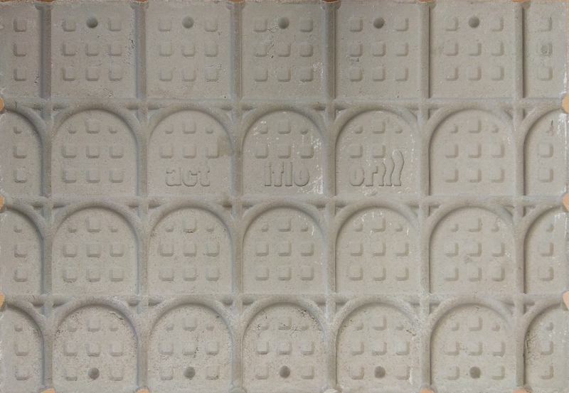
Here is an image of a fault free slab:
-
For the D435, the optimal resolution is 848x480. If you would like to achieve a higher quality image, the D415 model is better suited to scanning a small, non-moving object. It has around 2.5x the image quality of the D435 and its optimal resolution is 1280x720. D415 has a smaller field of view than the D435, but that should not make a difference at the close range that you are scanning the hole from.
Intel has a best-practices guide for tuning the 400 Series cameras.
If you want a process that can provide more detail than just the solid 3D mesh, software called Artec Studio can be used with another program called SOLIDWORKS via a plugin called Geomagic for SOLIDWORKS. The Geomagic plugin enables you to take a 3D model and convert it into CAD details and perform operations such as checking for deviation by comparing the scan to a 3D model.
https://www.artec3d.com/3d-software/solidworks-cad
-
Hi again,
The official RealSense blog published an article on using RealSense cameras in construction, with a link to a paper proposing use of the cameras for inspection. So I thought I would send you the link, as it seemed relevant to the analysis work that you do.
Please sign in to leave a comment.
Comments
8 comments