Deviation in distance to a flat surface (Realsense 415, Python)
I am trying to use Realsense to measure the roughness of the surface in front of it and for that I have begun with pointing my Realsense 415 towards a perfectly flat floor in well lit, naturally bright (away from direct sunlight) area around 1.4 meters above the floor. I have leveled my sensor using a spirit level to ensure that it is horizontal.
Then, I am aligning the color and depth images after streaming the data in 848x480 resolution at 6 fps. In order to capture the best data, I am only considering the central 400 pixels in the 240th row of the aligned depth data. So only a single line of data, 400 pixels wide.
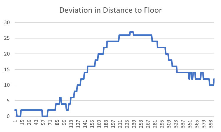
Ideally, I expect this data to be all of equal values with some minor noise, but it is not so. I subtracted the maximum value from the data array to obtain the height of each pixel above the floor and I get deviations upto 25 mm, which is huge. Below is the plot of this height value:
I am working with the understanding that Realsense gives the distance output that is distance of each point of object to the plane of the sensor and not to a single point in the sensor. I think I am right on this count.
What am I doing wrong? Do I need to make my sensor more perfectly level? Do I need to re-calibrate it?
Help please!
Edit: Forgot to mention that the floor is textured.
-
The floor is not particularly reflective: I am not able to see objects getting reflected off it, but if I shine a flashlight, there is a definite reflection. I have even tried by spreading a white paper sheet on the floor but with the same results.
I came across this post on improving accuracy (https://www.intel.com/content/dam/support/us/en/documents/emerging-technologies/intel-realsense-technology/BKMs_Tuning_RealSense_D4xx_Cam.pdf) and plan on ticking it off one by one. The first thing I want to do is to calibrate the sensor so that is ruled out.
I am still open to any other suggestions that I might be overlooking.
-
Calibrating the camera is certainly a good start, as the images generated by the camera may be negatively affected if the camera has received a physical shock (a hard knock, drop on the floor or severe vibration).
If the room is well lit then you could turn off the 'IR Emitter' option. This projects a semi-random pattern of dots onto surfaces to make flat-detailed surfaces such as doors, walls and desks more depth-readable by the camera. If the surface you are observing is well-textured then you should not need the assistance of the dot pattern, and the ambient light in the room will be sufficient to analyze depth. Turning off the IR Emitter can reduce 'RMS Error' (depth noise over distance) by around 30%.
-
Oops! I had written a wall of text in reply and it has vanished with my broken internet session. Let me try and cover it again.
I tried calibrating the device using a phone target. I don't think that has helped much. I am trying to loosely follow this post to improve the depth accuracy and have been reading a lot of stuff that has me utterly confused. I have the following queries. It would be very kind if you could shed some light:
- I am accessing my depth values through python code. Any changes that I make in the sensor configuration through the viewer application should reflect in the python output too, right?
- I recall reading somewhere that a 2% error in depth may be expected. Does that mean that the deviation in the distance to the flat floor that is nearly 1 m below the sensor within normal range? I am disinclined to believe that because while the inaccuracy is more likely to be random, my errors have the same trend for each pixel. Am I right in thinking that my issue lies in configuring my device better?
- Since my target would be in a bright, naturally lit area, what else can I try apart from turning the internal projector off. I tried setting the 'A Factor' to 0.18 based on this post, but I am yet to see any positive results.
- Lastly, but most importantly, I came across this website that claims that Realsense depth cameras can be better calibrated to yield results that are beyond what realsense claims. What is the official take on this and should I give it a shot?
Thanks in advance for your patient replies!
-
1. Changes in the Viewer options would change how the Viewer interprets the camera data. I would not expect a Python program to have its output automatically changed because the Viewer settings have changed. The Python program would have to alter the settings with its own code to see its own interpretation of the camera stream data.
The main situation where I would expect changes to be automatically reflected in both the Viewer and a Python program is if a new calibration of the camera extrinsics is written to the camera, using software such as the Dynamic Calibrator tool.
2. The best achievable accuracy with the 400 Series cameras is less than 1%, though around 2% may be the more commonly achieved range. There may be improvements that can be gained with changes to configuration or the environment that the camera is in. Intel's white-paper document on depth testing methodology may be useful if you have not seen it already.
https://dev.intelrealsense.com/docs/camera-depth-testing-methodology .
With the 400 Series cameras, the error scales with distance, with the error factor increasing as the observed object is further away from the camera lens. An example of how error scaling over distance can be expressed in mm: With an accuracy value of less than 1% of the distance from the object (like with the 400 Series cameras), if the camera is 1m from the object then the expected accuracy is between 2.5mm to 5mm.
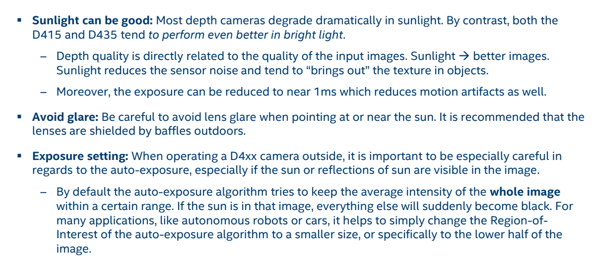
3. The RealSense 400 Series cameras are different from other depth cameras in that they perform even better in strong light. The image below contains advice on using the camera in strong light.
4. Intel aim to provide a range of different configurations for the 400 Series cameras (such as the set of pre-made Visual Presets) but they cannot cover every possible scenario. There is certainly plenty of opportunity for users to come up with their own optimizations, whether through changes to the open-source code or using other hardware (e.g custom-made circuit boards, external shutters, etc) with the camera hardware.
For example, in the new FRAMOS D435e industrial camera, FRAMOS added their own custom "GigE" processing board inside the camera casing alongside the standard Intel Vision Processor D4 board to add additional capabilities to the camera hardware, and other specialized features such as waterproofing / dustproofing and the ability to trigger the camera via an external power connector.
-
Regarding Point #1, I don't seem to find any documentation in Python part of Realsense code to capture data with all those parameters. And I am not really conversant with C++ to try that out.
I might consider saving my data through the viewer application and writing code for processing the Viewer output according to my requirements. I am currently able to save a frame in png as well as raw formats but I am looking for a way to access and read the raw files. I don't really need to work with bag files right now since a frame of data is all I need.
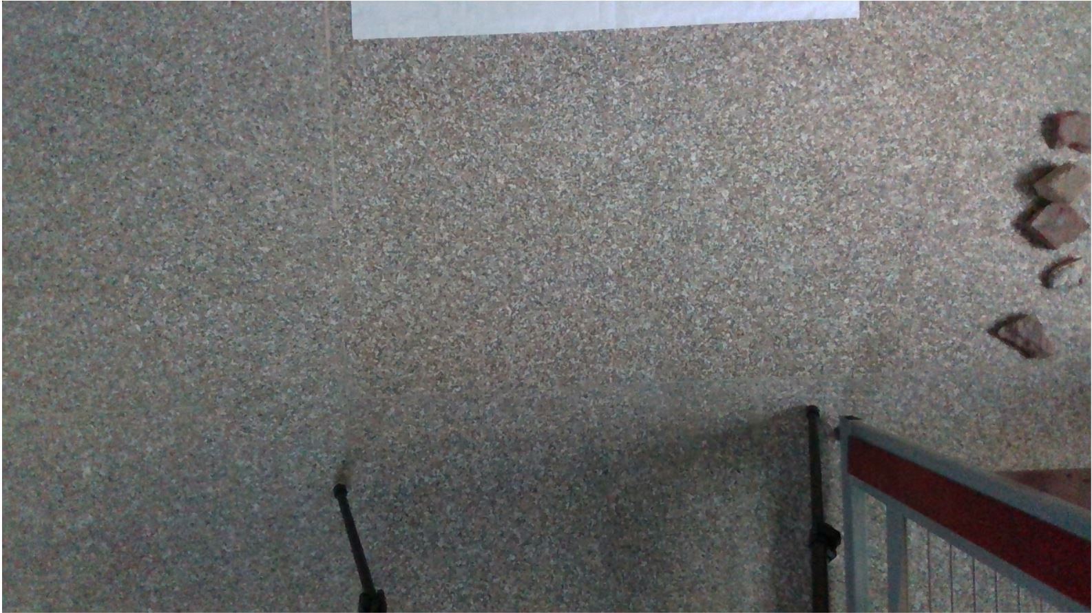
For the sake of completeness, I am attaching the Histogram Equalized version of my depth image captured from viewer and the corresponding RGB image. While the colors of the depth image don't directly correspond to a distance when histogram equalized, it is pretty noticeable that there is a definite pattern that is not corresponding to a flat surface, as is seen in the RGB image. I would love to have some insight into why that might be happening in the light of what we have discussed so far.

I can attach the corresponding raw file if required. Any help or insight in cracking this would be greatly appreciated!
-
Reading data from a .raw file would be tricky. The link below offers some C++ guidance on how it might be done.
https://github.com/IntelRealSense/librealsense/issues/2231#issuecomment-416814331
It may be easier to record a bag file and then use the rosbag editing tool to extract a frame or two and save it as a new small-sized bag.
https://github.com/IntelRealSense/librealsense/issues/4764#issuecomment-526466915
Analyzing your provided images with my eyes, it seems as though the darker red area on the left side may correspond to a darkening of the carpet shade on the left side, probably because of light being shone unequally on that area (more light on the center and right than the left).
The simpler way to describe the difference is to think of how the carpet would look if a glass of red wine had been dropped on the left side, and the stain pattern it would leave.
-
With regards to reading data with a defined sensor configuration and files, I have found the following and am writing it here for anyone who might be in a situation similar to mine:
In place of trying to figure out the calls to various parameters of sensor using Python, simply set up the viewer with desired custom settings and save some data in a bag file using record option (what the data is, is totally irrelevant). Then use this bag file as to look up for settings while calling the sensor from Python code using the syntax:
cfg.enable_device_from_file("sample.bag")
This is taken from the sample code on applying depth filters available at: https://github.com/IntelRealSense/librealsense/blob/jupyter/notebooks/depth_filters.ipynb
Also, the raw file is simply an array saved in the format it was captured. In my case it was a 640x360 array of 16 bit unsigned integer, without any headers or extra information. This can be accordingly called and read using code or image processing programs. The thing to note is that when saving a raw file from viewer, there is no option to save the full resolution image from the sensor in raw format. So, this approach does not serve my immediate purpose.
Next, I am still stuck with what I perceive to be a calibration issue. When sensing a depth for a completely flat surface, if I am getting deviation in some fixed pattern at all times, there should be a way to define this flat surface as an ideal surface and calibrate accordingly, the way most DSLRs do with custom white balance settings. Maybe I will try subtracting this depth map (flat surface) from my depth map with test objects and see what kind of results it gives me.
Also, as note to your reply: the flat surface is a granite floor with random, natural micro-patterns, I was hoping that this would serve as a good object for realsense. I am going to try the same with a flat wall today and see where that leads me.
Thanks for your patience!
-
Thanks so much for the detailed feedback!
It occurred to me that your granulated floor pattern actually resembles the ideal image for camera calibration with a textured surface. The important thing with such a surface is that the IR Projector is turned off (whereas you would have the projector turned on for a flat textureless white wall). The Chief Technical Officer of the RealSense Group at Intel (agrunnet) gives advice on the subject in the link below.
https://github.com/IntelRealSense/librealsense/issues/1267#issuecomment-372715603
Please sign in to leave a comment.
Comments
9 comments