edge detection problem in Intel realsense D455 depth mask
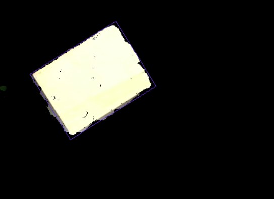
Hi i am trying to do a object detection using D455. It is is mounted right above the object facing downside. I have used clipping distance method to remove the background and mask it on color frame. after that using opencv I am making (purple) bounding box on a object in this case its box.
Problem is that at edges of box its also consider some background part even after giving the clipping distance and my opencv logic consider it as part of box and include in bounding box. I have uploaded a image for the reference. how can i exclude the background portion at edges of box to get a perfect bounding box on my object.
Any suggestion/solution would be appreciated.
-
H Valay Patel The rs-grabcuts RealSense OpenCV example program may provide some useful insights if you have not seen it already. It creates two masks, a near one and a far one.
https://github.com/IntelRealSense/librealsense/tree/master/wrappers/opencv/grabcuts
-
Hello Mr. MartyG
Thank you for your quick response. Actually yesterday I have tried rs-grabcuts but haven't got satisfactory results. In my background there is black color MS plate (15 mm thickness) on which i keep the box/object and the MS plate is kept at center of white table. Camera focus is on whole white table to accommodate big and small objects.
so rs-grabcuts sometimes consider the MS plate as object and white table as background and sometimes box as object and rest as background also makes my system slow (i5 8th gen, 8 GB ram, 256 SSD)
Can you please suggest any other solution or modification in rs-grabcuts to get a required output.
what i am trying to do is dimension and volume measurement of objects. mostly it is a boxes and plastic bags (irregular objects). I am aware of box dimension measurement program of realsense but i have restriction in camera mounting and can only use one camera. also tried box dimension measurement program but not giving results in my mechanical setup.
-
The camera will have difficulty capturing the black MS plate. This is because it is a general physics principle (not specific to RealSense) that dark grey or black absorbs light and so makes it more difficult for depth cameras to read depth information from such surfaces. The darker the color shade, the more light that is absorbed and so the less depth detail that the camera can obtain.
If you cannot change the MS plate then casting a strong light source onto the plate can help to bring out depth detail. If increasing the lighting is not possible (for example, if the plate is highly reflective) then coating the plate with a fine spray-on powder such as foot powder or baby powder will make it more detectable.
Regarding the box_dimensioner_multicam program, it can be used with a single camera despite the multicam name. The camera should be placed at the corner of the checkerboard (not directly above it) and also be placed at a distance of 0.5 meters from the observed object. Closer or further from the object than 1 meter can cause an incorrect / broken result.
-
Ok, Thank you for your suggestion. Even I was thinking of putting a light next to camera to get better exposure. Also i will try box_dimensioner_multicam program once again with some modification, only just want to know in box_dimensioner_multicam program what i can change so that once i calibrate it with checkerboard, I don't need to calibrate it again (from which variable i will get calibration data and in which variable i need to store it) if you can provide this info it will be very help full.
-
It is possible to modify box_dimensioner_multicam to not require the calibration checkerboard if you are only using one camera if you provide the intrinsics of the camera. A RealSense user did attempt to implement this method and their progress is discussed in the two case links below.
-
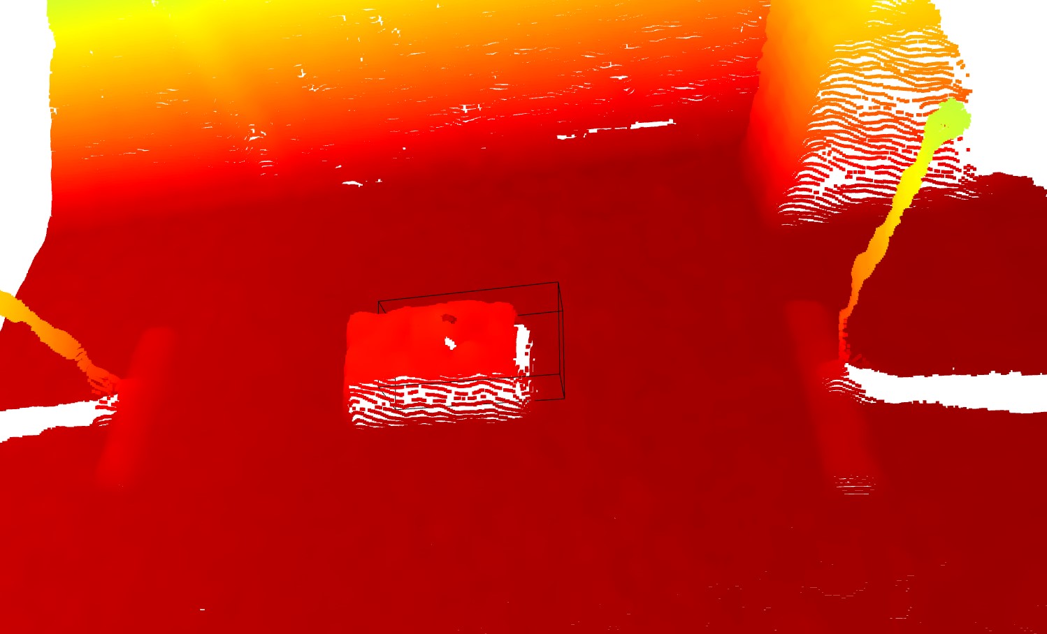
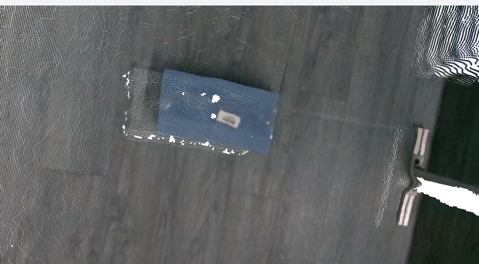
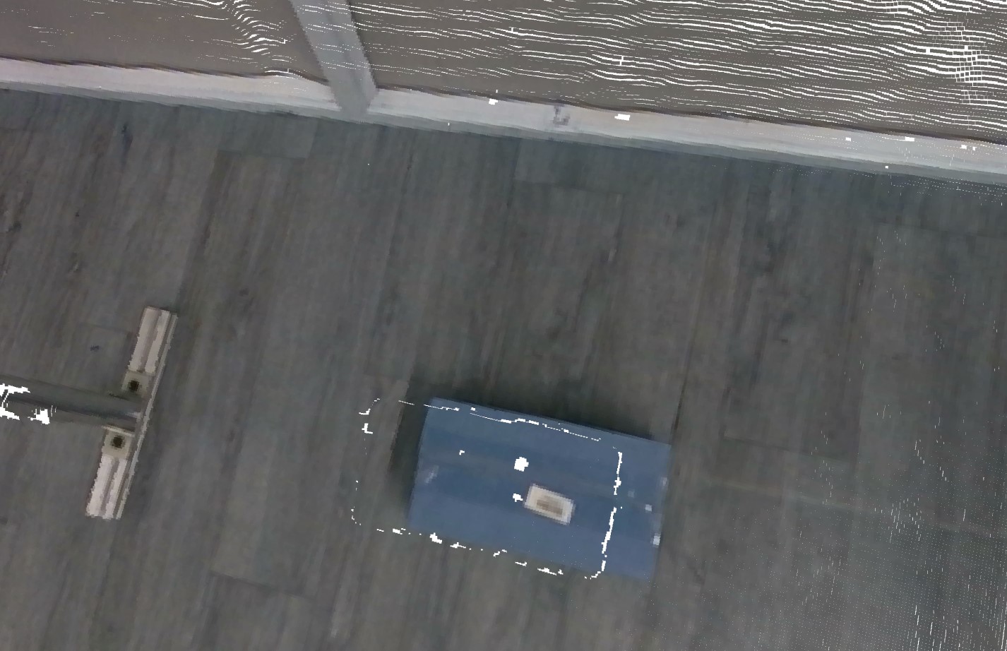
Hi MartyG, hope you are doing well. This time i need your help regarding 3d point cloud. Actually i am detection bounding box (length and width) of the parcel by processing rgb image with opencv and from depth frame i am getting the height of the parcel. but when i project the bounding box (corner pixels) data on 3d point cloud data i get a bounding box slightly offset (See first image). Even when i normally visualize the point cloud with rgb image, the rgb image seems some offset from point cloud data (see second and third image)
Is there any way to aligned this data and get a proper bounding box.
-
The bounding box seems to always be mis-aligned in the length direction but fits to the plate well in the width and height directions. It also seems to always be offset by relatively the same amount on the length axis.
A workaround cheat might therefore to be to add a minus-value offset to the bounding box's length value so that it moves back over the object and fits over it correctly.
Please sign in to leave a comment.
Comments
11 comments