3D Data (Step) D555
Hi,
to integrate the new D555 into our AMR, we need the 3D data of the camera, preferably in STEP file format. Unfortunately, I haven’t been able to find any 3D data anywhere. Could you please provide it?
-
Hi Eric Kraemer The official RealSense CAD files of cameras and depth modules are in .SLDPRT format. It is possible though to convert .SLDPRT to .STEP.
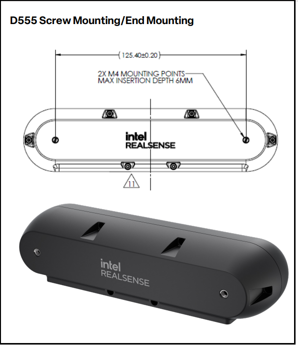
It typically takes some time after a new camera model's release for an accompanying CAD file for it to become available. In the meantime, it may be possible for you to create a temporary CAD representation of the D555 yourself though using its official measurements, which are 167 mm × 42 mm × 48 mm (horizontal width, vertical height and front-to-back depth respectively).
-
Hi Marty,
thanks for the quick reply! Actually, having the SLDPRT files would be even better :-). To properly integrate the camera into our AMR, the original CAD data would really be the best option. That way we can make sure everything fits precisely without having to rely on temporary models.
Best regards,
Eric -
You can keep an eye on the CAD file directory page at the link below for future updates.
-
Hi Marty,
this is really unacceptable. How can you release a new product that’s meant to be used in robotics and integrated into systems, but then not provide any 3D data? There isn’t even a dimensioned sketch of the external measurements, let alone the positions of the connectors. That’s truly a shame. -
Hi Eric, sincere apologies for the inconvenience. Whilst a D555 CAD file is not available at the time of writing this, as D555 uses the existing D450 camera circuit board you may be able to use the D455's SLDPRT CAD file as a temporary substitute for testing integration into a system as it contains the D450 camera module that D555 also uses.
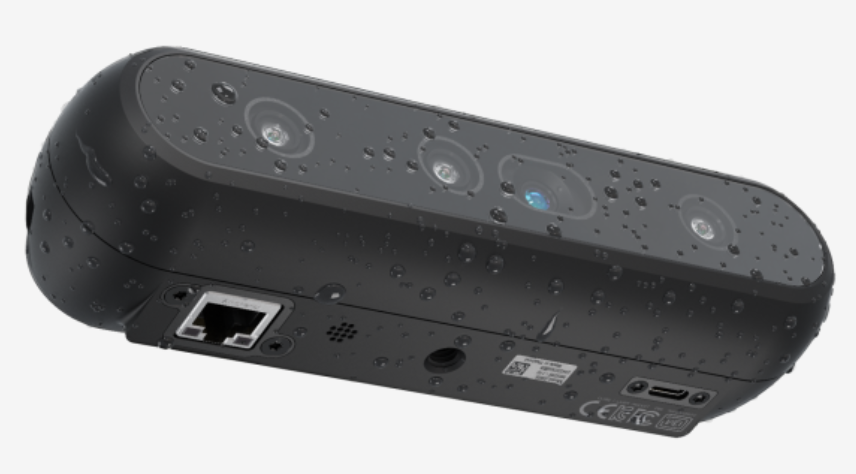
The image below shows the approximate position of the D555 connectors, though their position measurement information will not be on the D455's CAD model as the connectors are on the RealSense Vision SoC module which is a different ASIC board to the Vision Processor D4 one that D455 has.
Please sign in to leave a comment.
Comments
5 comments