Issue with Measurement Accuracy of D456 Camera When Mounted Upside Down and with a Pitch Angle
Hello Intel family,
I have noticed that the measurement accuracy of my D456 camera is affected when it is mounted upside down and tilted with a pitch angle.
To investigate the cause of the inaccuracy and the correctness of my point-cloud-transformation, I measured a fiducial marker:

When performing this measurement with the camera mounted upside down and pitched at 7.5 degrees, I obtained the following results for the four corners and the center of the marker, before and after transformation of the point cloud:
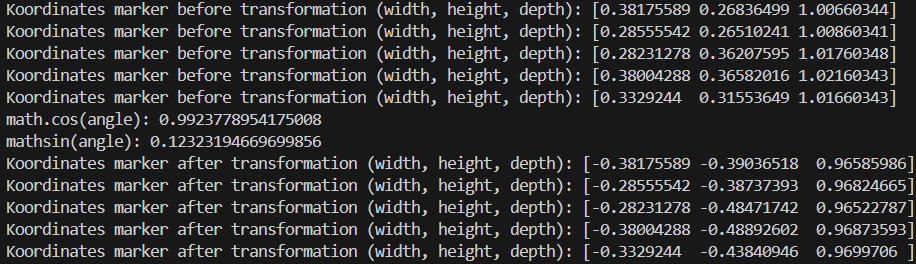
Examining the transformation results, it appears to be functioning correctly, as the depth values are all very close, around 0.966 m. This indicates that the marker is recognized as a plane after the transformation, as expected. However, the ground truth depth is approximately 1.0 m, which suggests there is an accuracy issue (about 0.034m) with the camera’s measurements.
Performing the same measurement with the camera mounted upright on a tripod, horizontally at a pitch angle of 0°, I obtained the following results for the four corners and center of the marker:
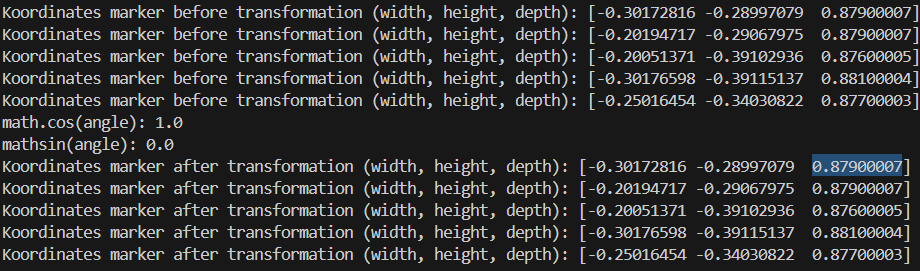
In this case, the marker is again detected as a plane with a depth of approximately 0.878 m, which is very close to the ground truth of 0.875 m. Therefore, I consider the measurements from the camera mounted upright with zero pitch angle to be valid.
So my question is: Are you already familiar with this behavior and know how to address it?
- Is this an issue that can be addressed through camera calibration?
- If so, which type of calibration would you recommend?
- Is it incorrect to rotate the Open3D point cloud directly, since intrinsic camera parameters aren’t accounted for in that process? Would it be better to apply the rotation to the depth image instead? If so, how can I do that?
Or could it be that I’m making a mistake somewhere?
This is how I am obtaining the depth frame: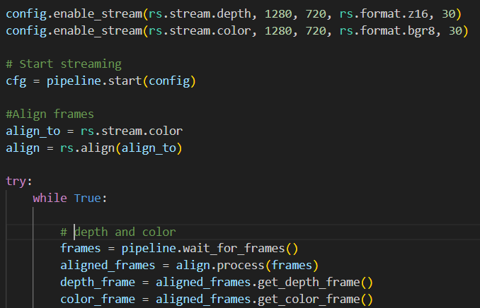
Thats how I call my transformation function:
-->Here I'm using open3d point-cloud.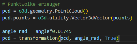
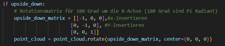
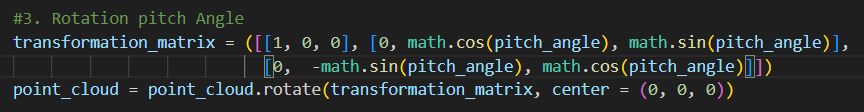
In the transformation function I rotate the point-cloud:
-
Hi Laurin Steiner As you mentioned, if the image is rotated then the intrinsics are not rotated with it. So all calibration data and parameters need to be updated.
Intel recently implemented a rotation filter post-processing filter to do this with depth, infrared and color frames.
https://github.com/IntelRealSense/librealsense/pull/13499
This rotation filter is currently only available when installing the development branch of the SDK.
https://github.com/IntelRealSense/librealsense/tree/development
-
RealSense users who wish to access the rotation filter through the RealSense ROS2 wrapper can find information about doing so here:
https://github.com/IntelRealSense/librealsense/issues/6023#issuecomment-2545597941
-
You are very welcome!
There is not a filter for setting IMU angles. However, there is an example of Python code for retrieving IMU pitch, roll and yaw here:
https://github.com/IntelRealSense/librealsense/issues/4391#issuecomment-510701377
In theory, you could set your own pitch value by replacing the code that retrieves the pitch value from the camera with your own custom value.
-
You can also find the angle of the camera relative to the floor plane without the IMU by using a plane-fit algorithm.
https://support.intelrealsense.com/hc/en-us/community/posts/360050894154/comments/360013322694
-
Thank you for the methods to retrieve the pitch angle.
What I’m still not quite clear about is how to effectively use the obtained pitch angle together with the depth image.
Is it important to consider the changing intrinsic camera parameters in this context?Is there a way to account for that, or is it even necessary?
Or is it sufficient to simply rotate the resulting point cloud afterward, as I have been doing so far? -
It is not necessary to perform special calculations to take the tilt angle into account. The camera's stereo depth algorithm can generate depth no matter what angle the camera is rotated to.
When the camera is physically rotated, the intrinsics will automatically be taken into account and you do not need to do anything. It is only necessary to update the intrinsics using the rotation filter when the image has been rotated too - for example, rotating the camera 30 degrees and then rotating the image 30 degrees in the opposite direction so that the image is not tilted.
-
Ah, okay, I think I understand now.
So, I wasn’t actually doing anything wrong initially, was I?What I was trying to do was to rotate my obtained Open3D point cloud so that from the rotated point-of-view, the camera would have zero pitch and roll angle. Since I was applying the rotation directly to the point cloud and not the image, I don’t think my approach was incorrect, right?
However, I’m still struggling to understand where the inaccuracy is coming from. Do you have any experience or insights that might explain what I might be missing here?
Thank you very much for the help!
-
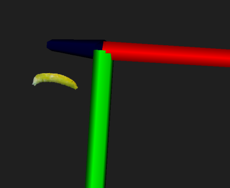
As the official RealSense pointcloud example programs for C++ and Python incorporate the ability to rotate the pointcloud's viewpoint (which is not altering the depth data itself), you should be okay with rotating your cloud without performing adjustments. However, rotating the pointcloud to a different view tends to cause distortions in the cloud. For example, the images below show what happened to a pointcloud of a banana when the cloud was rotated to a side-on view.
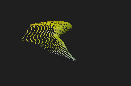
In the banana case that these images are taken from, an Intel RealSense team member offers advice for dealing with the distortion.
https://github.com/IntelRealSense/librealsense/issues/3741#issuecomment-485588689
-
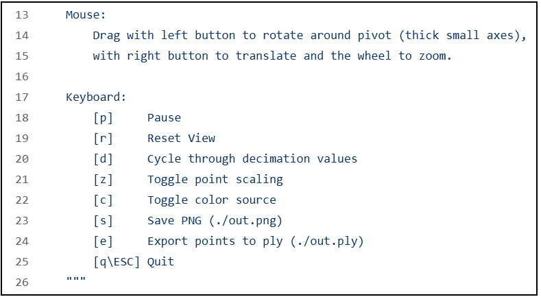
The SDK's Python example program opencv_pointcoud_viewer.py has a mechanism for rotating the pointcloud with the left mouse button.
-
Unfortunately, I wasn’t able to make any progress rotating the point cloud.
Therefore, I decided to further investigate the camera’s inaccuracy today.To do this, I mounted the camera horizontally and in the correct orientation on the application, and compared the results with two measurements taken using tripods.
From this, I found that the measurement taken via the application is inaccurate by about 10mm to 15mm in depth. For this measurement, the camera height was 420mm. The two tripod measurements, however, are accurate when compared to the ground truth. The camera heights for the tripod measurements were 120mm and 480mm, respectively.
I’m now wondering if the inaccuracy might be related to the camera height. However, since one tripod measurement is taken lower and the other higher than the application measurement, I suspect the inaccuracy is due to something else.
Could it be that the mounting method influences the accuracy? For the tripod measurements, I used the 1/4-20 UNC thread mounting point, while for the application measurement, I used the M4 thread mounting points.
Alternatively, there might be some environmental factors affecting the accuracy that I’m unaware of. Below are the environments for each measurement from the camera’s point of view:
Application measurement ( camera height 420mm):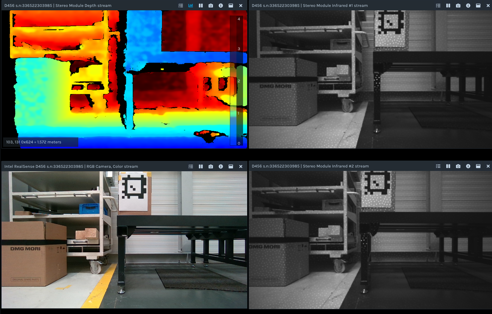
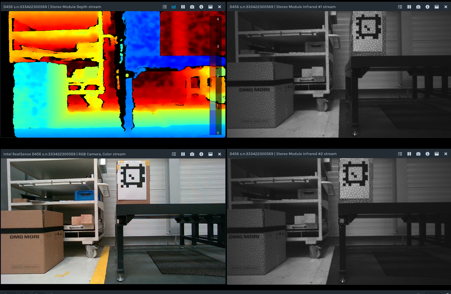
Tripod measurement ( camera height 480mm):
Tripod measurement ( camera height 120mm):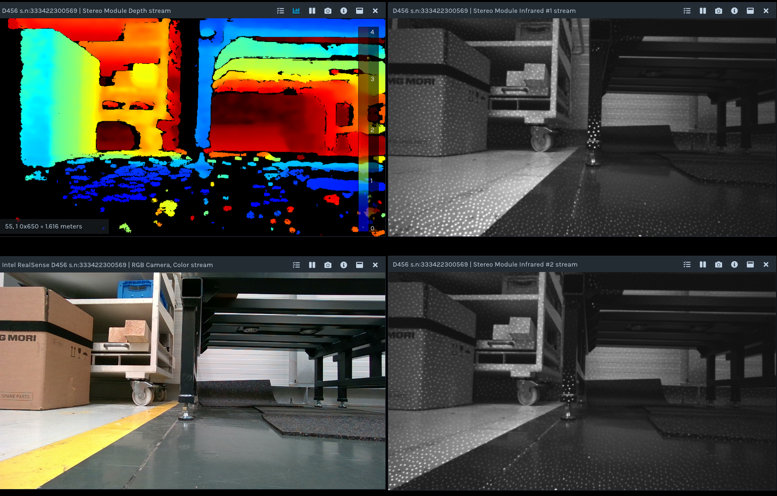
-
In theory the mounting method used should not make a difference. There was a past case though when a camera performed worse when a USB cable was attached to the camera firmly using the screw-threads either side of the camera's USB port. Results improved when the screw-threads were loosened. So a similar effect could be occurring with the pair of M4 mounting screw-threads on the rear of the camera, which are very similar to the USB port screw-threads.
It is not ideal that the floor is dark and reflective, as the camera will have greater difficulty reading such surfaces. In this particular case it does not seem to be causing a problem with the depth image taken with the tripod though.
-
Ah ok, then I think this might be my problem.
After conducting additional tests today, it seems confirmed that the measurement inaccuracies consistently occur when the camera is mounted using the M4 screw threads, regardless of the position of the camera in space.
Unfortunately, mounting the camera with the M4 screw threads is my only option. Could you please advise if there is any solution to address this problem? Also, could you explain what exactly is causing these inaccuracies? Then I might be able to control them.
Thank you very much for your assistance.
Thank you very much for your help. -
In that case, the screw-threads were loosened but not removed entirely from the mounting holes. They were just undone a little so that the tips of the screws were not fully buried into the back of the hole. So you could try unwinding the screws a millimeter and see if the camera can remain firmly attached to the mounting point whilst still providing a good image.
This phenomenon was only reported once and is not a normal characteristic of RealSense cameras. The camera in that issue was a D455, which is very similar to your D456 (the difference being the D456's environmentally protected casing).
-
If the problem is related to the insertion of metallic screws into the casing, the solutions I can think of is the loosening of the mounting screws a little, or having some kind of intermediary mounting plate inbetween the mounting point and the camera mounting holes (attach the plate to the mount and the camera to the plate).
Is there any possibility of attaching the camera to the mounting point by wrapping rubber bands tightly around the camera and the mount to fix it in position without using the mounting screws?
-
Thank you for the advice. I believe that mounting the camera using an intermediate mounting plate could help, as the inaccuracies seem to stem from mechanical stress caused by the original mounting plate not being perfectly flat. This results in the camera deforming, which in turn affects the accuracy of the distance measurements.
Does Intel provide any mounting standards to address this issue? Alternatively, is there a solution that involves compensating for the deformation by adjusting the distance data accordingly?
-
Intel provide the standardized size of the pair of mounting screw-thread holes on the rear of the camera (M4 for D455-class cameras like D455 and D456). Because it is a standard size, the customer then has the freedom to chose a mounting solution that will suit their particular project.
For the purposes of installing an intermediary plate between the original plate and the camera, an adaptor mount may work. The search term m4 camera mounting plate adaptor can be used to research it.
In regard to compensating for the deformation, you could try performing a calibration of the camera and saving the updated calibration to the camera hardware. If you are using both depth and RGB streams then the Dynamic Calibration tool is the appropriate one to use. The Dynamic Calibration program for Windows can be downloaded here:
If you have an Ubuntu computer then page 14 onwards of the tool's user guide has installation instructons.
If you have access to a Windows computer then you can do the calibration in Windows and then transfer the camera to an Ubuntu computer, as the calibration is stored inside the camera hardware and so it does not matter whether the calibration is performed on Windows or Ubuntu. I would recommend the Windows version if you have the option to do so, since that version is a pre-built, ready-to-run executable.
-
I have completed the calibration process, but unfortunately, one camera still shows inaccuracies even when mounted with loosened screws. Is it possible that the camera is permanently deformed and cannot be corrected?
I also have one more question regarding the mounting technique: Does Intel provide any guidelines on the required surface flatness or surface texture for mounting?
Thank you for the help! -
It is very unlikely that the camera's sensors would have been physically distorted by the mounting screws. You could try resetting that particular camera to its factory-new default calibration values in the RealSense Viewer using the instructions here:
https://github.com/IntelRealSense/librealsense/issues/10182#issuecomment-1019854487
There is not specific guidance about the flatness of a mounting surface but it would be ideal for it to be uniformly flat instead of partially sloped, otherwise one side of the image could potentially have slightly different distance values than the other side of the image even when the real-world area being observed is the same distance away from the camera.
-
Hello MartyG,
I have another question regarding the accuracy of the D456 depth camera.
Since I was unable to log into my old account, I’ve created a new one to post this question.
Currently, I’m trying to evaluate the accuracy of my system. To do this, I’ve compared several D456 cameras to ensure that any inaccuracies I observe originate from my own system and not the cameras themselves.
During this process, I noticed that the depth measurements vary between different D456 units. This became apparent when I measured a fiducial marker using multiple cameras, recording the depth values at the four corners and the center of the marker. All cameras were set to their factory defaults during the measurements.
The two cameras produced the following results:
Camera 1: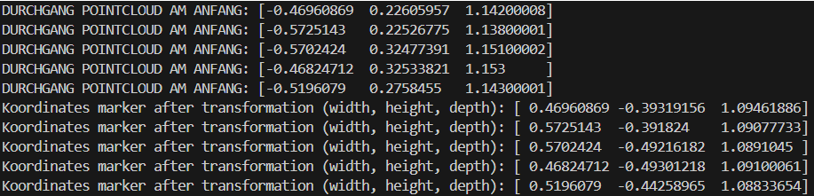
Camera 2: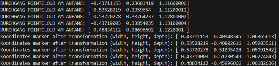
It can be observed that the transformation is functioning correctly, as the differences in width and height are both approximately 100 mm — matching the actual dimensions of the marker. So the proportion of the marker is not influenced, but the position in space is measured differently.
Therefore, despite both cameras being mounted in exactly the same position, the 3D measurements of the marker’s corners and center differ significantly between the two units.
I would like to know whether it is normal for two different D456 cameras to produce such varying depth results under identical conditions.
What could be the reason for this discrepancy?
One possible explanation I thought about could be the systematic depth error inherent to the Intel RealSense D456. In a previous analysis, I found this error to be roughly 2% of the measured depth. Is this value approximately correct, or can the systematic error vary between different units?
Additionally, is there also a systematic error in the width measurement that should be taken into account?
Another possibility I considered was recalibrating the cameras using the Dynamic Calibration Tool, as you previously suggested. Unfortunately, this did not lead to an improvement in the results.
Thank you for your support
Kind regards
Laurin -
Ideally multiple cameras should perform relatively equally, though a camera can become miscalibrated if it receives a physical shock such as a hard knock, severe vibration or drop on the ground. If you are unable to perform a calibration then you could try using the factory-default reset procedure you used on a camera earlier in this discussion on all the cameras to see if their results become more equalized.
https://support.realsenseai.com/hc/en-us/community/posts/41658952739091/comments/41932751565843
Error starts at around zero at the front glass of the camera and increases linearly over distance. Most RealSense 400 Series models have depth error of around 2% at 4 meters distance. Whilst error can reduce below 2% as the distance of an observed object and the camera reduces, in real-world use 2% is a reasonable expectation for accuracy.
The D405 camera model has enhanced accuracy compared to other 400 Series models and is the only model in the range officially described as having 'sub-millimeter' accuracy. It is not equipped with an infrared pattern projector or the D456's water and dust resistant environmental protection casing or its light-blocking filters though.
-
What does "relatively equally" mean in this context? Based on the values shown in the images above, is a depth difference of about 30 mm acceptable? And is it also normal for the width estimation to differ by up to 30 mm? My measurement range is between 0.5 m and 2.0 m.
As mentioned earlier, I’ve already reset the cameras to their factory settings and also performed Dynamic Calibration. Unfortunately, neither approach has led to any noticeable improvement.
Are there more accurate calibration methods thanDynamic Calibration? Or is there a procedure to compensate the differences of the D456 camera? -
Every RealSense camera has unique calibration values because of the manufacturing process at the factory. So by 'relatively equally' I mean that the results from each individual camera may not be identical to each other when compared but should be very similar.
If you need to calibrate both depth and RGB together then there is not an alternative calibration tool to Dynamic Calibration to do so. If you only need to calibrate depth then the On-Chip and Tare calibration tools should work just as well as depth calibration in the Dynamic Calibration tool.
What you could try is opening the Calibration Data window in the Viewer (the one used for calibration factory-reset) whilst your most accurate D456 is plugged in but do not click the factory reset button. Instead, note down the values displayed for each calibration parameter. Then open the Calibration Data window for each of your other cameras, change the displayed calibration values to the ones that you noted down from your most accurate camera and then click Write Table to write that manually entered calibration to the camera. This should help to ensure that your several D456 cameras share the same calibration values.
If a problem occurs with this process (such as the accuracy becoming worse) then you can always use the factory reset to reload the default calibration values back onto the cameras.
Please sign in to leave a comment.
Comments
28 comments