Stereoscopic 3D measurments
Hello,
Our company would like to make 3D measurements like in this video : https://youtu.be/Xa_Srs5RnVk?t=137
Do you know a depth camera below 3 000 €, allowing 5% error max on a 3D measurement?
Thank you in advance !
-
The RealSense 400 Series cameras have an error rate of 2% or less, and start at $149 for the RealSense D415 model. If you anticipate that your project will have fast camera movement or be tracking fast objects then the $199 D435i model is recommended if you need to purchase a camera immediately.
If you are able to wait then the best option for a project involving fast motion will be the new $239 D455 model, which is available to pre-order now. It has improved accuracy over distance than the D435 models by a factor of two, making it ideal for accurately observing objects from a distance, and it has a fast shutter on both the RGB color and the depth sensors.
-
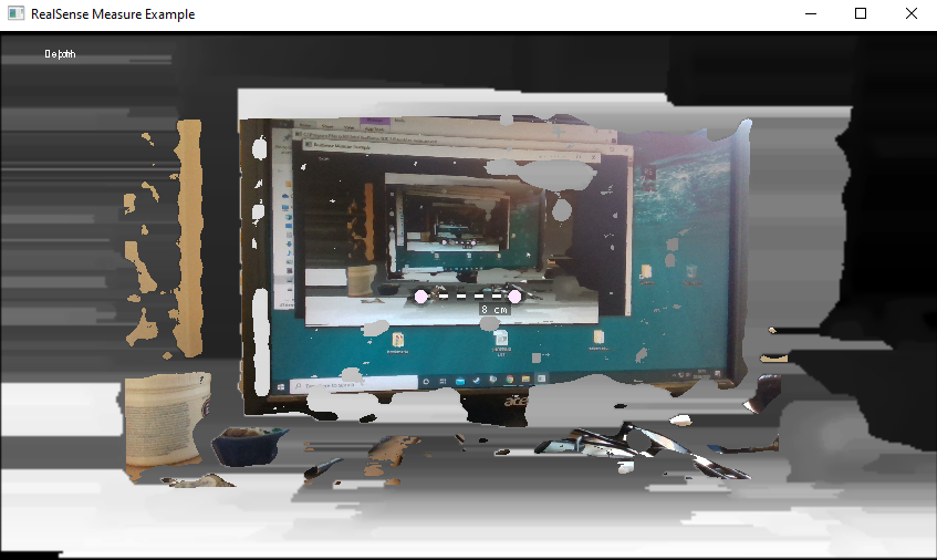
The RealSense SDK has a pre-made example program called Measure that automatically updates a measurement between two points of an object at the centerpoint of the camera's field of view. As the camera is moved, the measurement on-screen updates as it measures whatever comes into the camera's centerpoint.
It is probably not going to provide the accuracy that you need though. A more advanced solution may be to take a 3D scan of the threaded object and compare it to a perfect 3D model template of the object. In this way, deviation analysis can be done to see if there are manufacturing errors.
To do this, software called Artec Studio can be used with another program called SOLIDWORKS via a plugin called Geomagic for SOLIDWORKS. The Geomagic plugin enables you to take a 3D model and convert it into CAD details and perform operations such as checking for deviation by comparing the scan to a 3D model.
https://www.artec3d.com/3d-software/solidworks-cad
A less advanced approach would be to use open-source software called CloudCompare to compare a point-cloud scan of the object with an ideal point-cloud scan.
-
I also recalled a previous case in which the subject of measuring between two points had been discussed.
-
Thanks a lot for your replies. You are helping me so much !
I don't think deviation analysis is the solution for us because we are not trying to see defaults but only to see the diameter of threaded rods in order to know if it is M8, M10, M12 etc...
However, the pre-made example program called Measure seems perfect ! It is exactly what we want to do but we do not need real-time measuring. We are going to do post processing measurements.
The final stage of my study is to be sure that I can have the precision I need. As we can get as close as needed to the target, I think the D435 is the perfect choice for our application because it has a minimum depth distance of 0.1m. What do you think ?
-
Although the D415 has better accuracy over distance, because the error curve increases linearly over distance from the camera there will be negligible difference in accuracy between the D415 and D435 when doing close-range sensing. So yes, if you use the D435 then you can take advantage of its lower minimum distance.
For the D435 the optimal depth sensing resolution will be 848x480. You may be able to attain additional accuracy by setting the camera to use a custom preset configuration called 'High Accuracy', which shifts the balance of the camera configuration to favor accuracy. You can also define your own custom preset especially for your project.
https://github.com/IntelRealSense/librealsense/wiki/D400-Series-Visual-Presets
Alternatively, there is also a pre-made Short Range configuration preset that you could try.
-
Ok, so based on what you said, the D435 would be better because we will only do close range sensing.
Thank you so much for all the information about presets and configurations, it will help me very very much.
I will try the high accuracy preset and the short range one to see which is best for my application.
-
So as promised, I post up my tests.
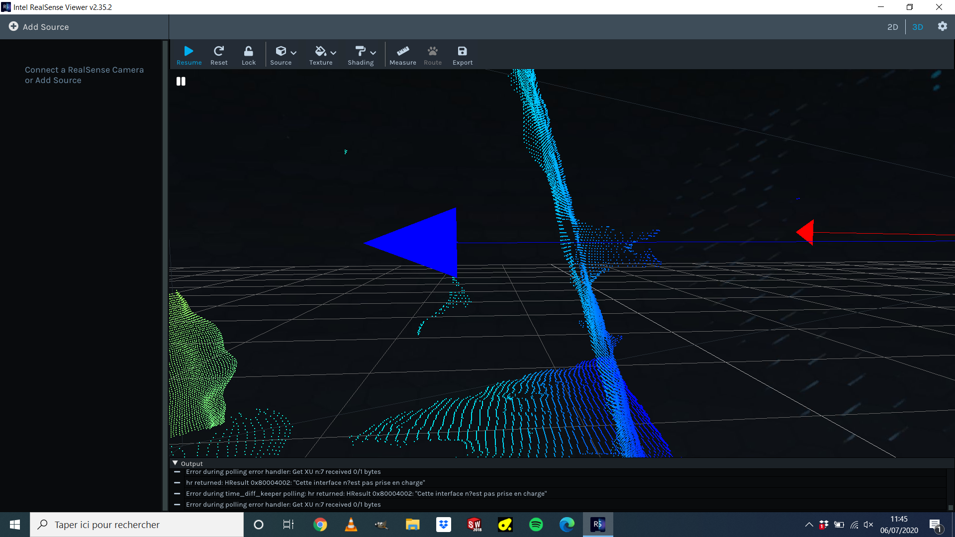
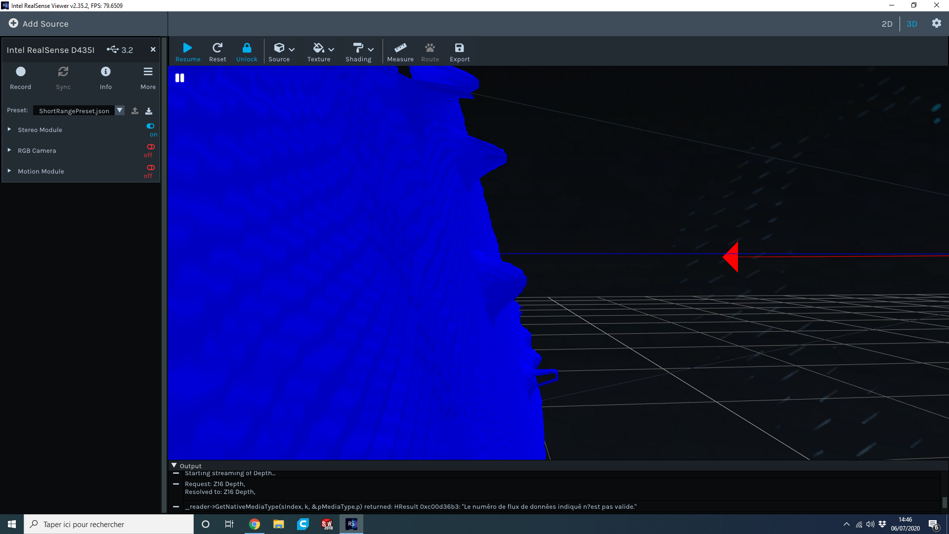
There were not very conclusive. I tried "High accuracy" and "Short range" presets. I did the dynamic calibration with the "Dynamic Calibrator" tool and the "on-chip calibration" on the "Intel RealSense Viewer" software. But I only have not enough precise point clouds to measure the diameter of the threaded rod.
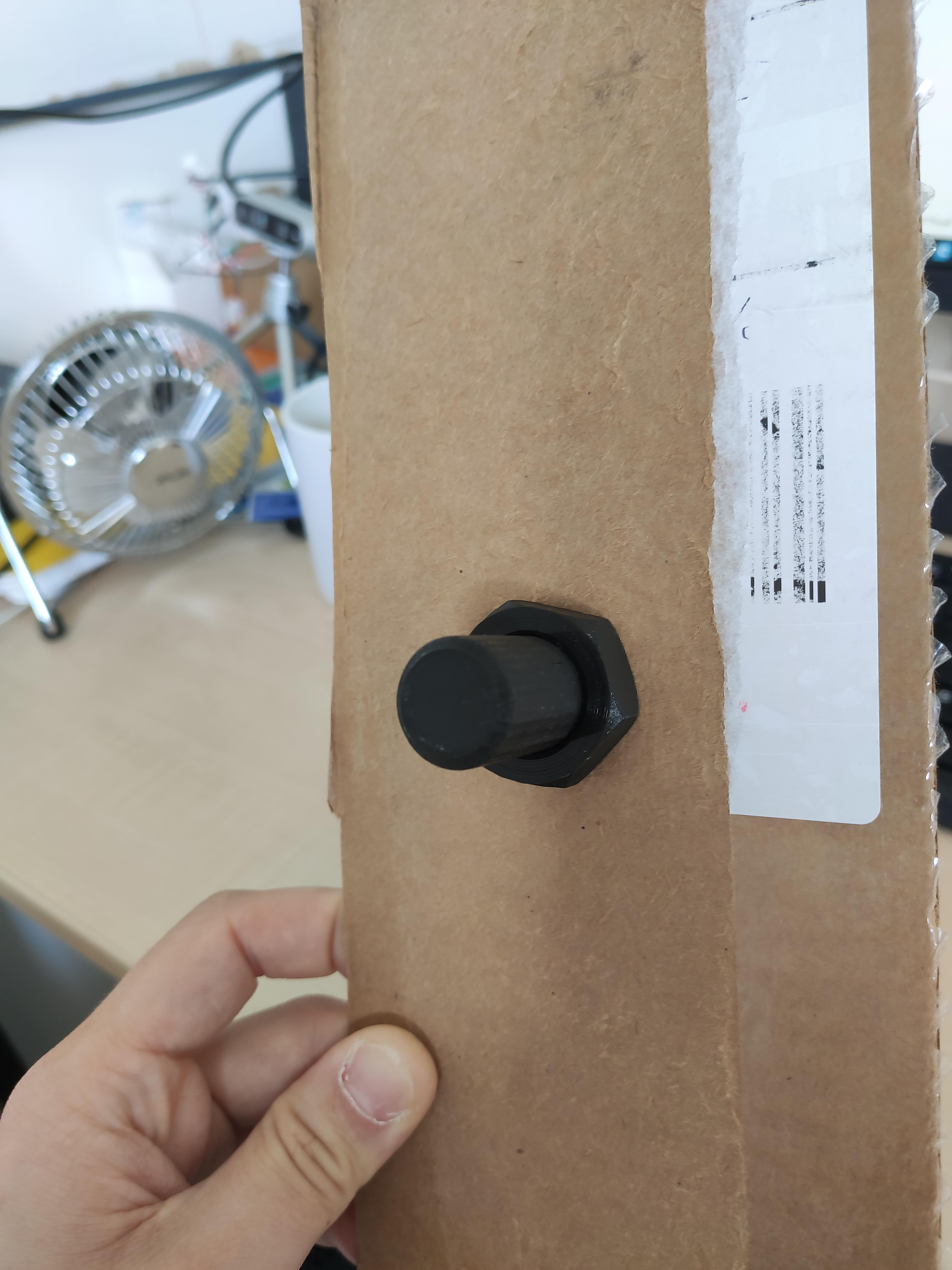
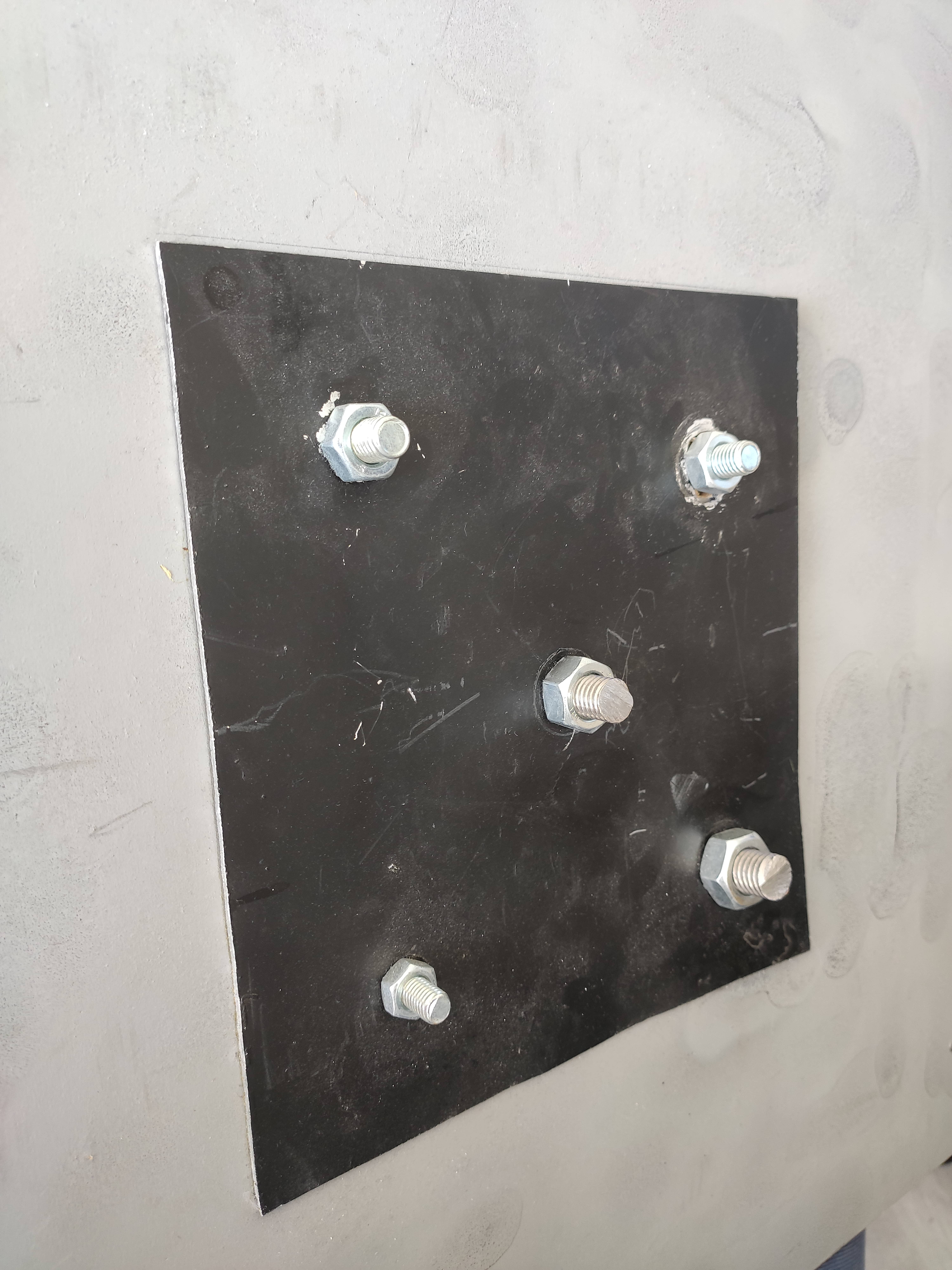
Here is a photo of the rod :
Here is a snapshot of the point cloud :
I think I expected to much of the cam. Maybe I should do this by creating a point cloud by scanning the threaded rod with software like Dot3D ? I thought that I could measure a tiny object like a rod (15-20mm) but I think it is too tiny for the cam and the resolution is not enough to do real-time measurements.
-
The problem may simply be that the rod is black. Black or dark grey surfaces are difficult for depth cameras (not just RealSense) to see because there is a general physics principle that these colors absorb light instead of reflecting it back. The darker the shade of black, the less visible the object is.
This principle was demonstrated in another case yesterday where a black chair was having its depth read:
https://github.com/IntelRealSense/librealsense/issues/6757
A couple of approaches to the problem would be:
- Applying a fine spray-on powder such as baby powder or foot powder to the object to increase its visibility.
- Project a strong light-source onto the rod to aid the camera in reading its depth.
-
Shiny surfaces are tricky to deal with if you cannot apply anything to the bolts. If you could, then you could have used a professional 3D scanning spray on them that is used for situations such as making 3D scans of jewelry.
https://www.laserdesign.com/3d-scan-spray/?language=en_US
An alternative to coating the object is to apply an anti-glare filter such as a polarizer over the camera lens. Intel have published a paper on the subject of physical optical filters.
https://dev.intelrealsense.com/docs/optical-filters-for-intel-realsense-depth-cameras-d400
-
The subject of point cloud "ghost noise" is discussed in the link below.
https://github.com/IntelRealSense/librealsense/issues/4553
Advice about reducing such noise is given here:
https://github.com/IntelRealSense/librealsense/issues/3741#issuecomment-485588689
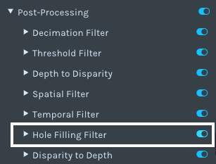
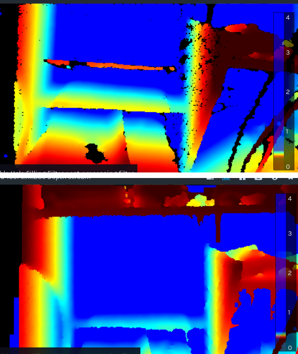
Regarding hole-filling: you may get less holes if you apply the Hole Filling post-processing filter to the image, as shown in the before and after example image below. It may still be necessary to use a physical optical filter too though, in order to give the camera some depth detail to improve in the first place.
-
I do not have any holes but I have hills instead of a bolt. The last depth map I posted is from the 5 bolts you see on the pictures.
Maybe I can tweak the depth step-size ? https://dev.intelrealsense.com/docs/tuning-depth-cameras-for-best-performance
-
Hello,
After a short good night of sleep, I have fresh questions ;)
I think the 2D example will not help me as it seems that I have not enough points to measure what I want (diameter of 10-20mm threaded rod like in the picture some posts above). Correct me if I'm wrong : I need to scan the target by moving my camera around the threaded rod and add as many points as I can to "increase resolution".
I already try Dot3D and after the scanning process finished, it gives me the same result as real-time : 5 ugly little hills instead of 5 threaded rods and nuts. You can see what I mean here : https://support.intelrealsense.com/hc/user_images/W6aYuXon8eGvWeVPdj-AZg.png
But a friend of mine told me that maybe the scanning software (Dot3D) doesn't reconstruct as I want the 3D object. He thinks that it try to build a mesh and smooth the surface. As a consequence, it differs from the real geometry of the rod and give a cone-like shape.
What do you think about it ? What is the issue : me (wrong procedure), the software (wrong settings) or the camera (not enough resolution) ? -
Regarding not having enough points to measure on the rod: if the depth data in an image is too low (too "sparse") then you can reduce sparseness by increasing the value of the Laser Power option.
However, if you do need a more detailed point cloud then you can build up a detailed cloud by moving the camera repeatedly around the object, using a technique called SLAM. Here's an example of Intel demonstrating this principle in 2015 by scanning a room with a handheld smartphone with a built-in RealSense stereo camera (the ZR300, the direct predecessor of the D435).
https://www.youtube.com/watch?v=Vpa8vKsapFk&feature=youtu.be&t=97
Having said that, you are more likely to get a 'lumpy' result with a point cloud scan than you are with a 3D model mesh. The LIPScan 3D software demonstrates the principle of putting an object on a turntable in front of a single 400 Series camera and building up a good quality model scan by rotating the turntable.
Please sign in to leave a comment.
Comments
26 comments